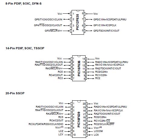
Features: Special Microcontroller Features:
• Precision Internal Oscillator:
- Factory calibrated to ±1%
- Software selectable frequency range of 8 MHz to 31 kHz
- Software tunable
- Two-Speed Start-up mode
- Crystal fail detect for critical applications
• Clock mode switching for low power operation
• Power-saving Sleep mode
• Wide operating voltage range (2.0V-5.5V)
• Industrial and Extended Temperature range
• Power-on Reset (POR)
• Wake-up Reset (WUR)
• Independent weak pull-up/pull-down resistors
• Programmable Low-Voltage Detect (PLVD)
• Power-up Timer (PWRT) and Oscillator Start-up Timer (OST)
• Brown-out Detect (BOD) with software control option
• Enhanced Low-Current Watchdog Timer (WDT) with on-chip oscillator (software selectable nominal 268 seconds with full prescaler) with software enable
• Multiplexed Master Clear with pull-up/input pin
• Programmable code protection (program and data independent)
• High-Endurance Flash/EEPROM cell:
- 100,000 write Flash endurance
- 1,000,000 write EEPROM endurance
- Flash/Data EEPROM Retention: > 40 years
Low Power Features:
• Standby Current:
- 1 nA @ 2.0V, typical
• Operating Current:
- 8.5A @ 32 kHz, 2.0V, typical
- 100A @ 1 MHz, 2.0V, typical
• Watchdog Timer Current:
- 1A @ 2.0V, typical
Peripheral Features:
• 6/12 I/O pins with individual direction control:
- High-current source/sink for direct LED drive
- Interrupt-on-pin change
- Individually programmable weak pull-ups/ pull-downs
- Ultra Low-Power Wake-up
• Analog comparator module with:
- Up to two analog comparators
- Programmable on-chip voltage reference (CVREF) module (% of VDD)
- Comparator inputs and outputs externally accessible
• Timer0: 8-bit timer/counter with 8-bit programmable prescaler
• Enhanced Timer1:
- 16-bit timer/counter with prescaler
- External Gate Input mode
- Option to use OSC1 and OSC2 in LP mode as Timer1 oscillator if INTOSC mode selected
• KEELOQ® compatible hardware Cryptographic module
• In-Circuit Serial ProgrammingTM (ICSPTM) via two pins
Low Frequency Analog Front-End Features (PIC16F639 only):
• Three input pins for 125 kHz LF input signals
• High input detection sensitivity (3 mVPP, typical)
• Demodulated data, Carrier clock or RSSI output selection
• Input carrier frequency: 125 kHz, typical
• Input modulation frequency: 4 kHz, maximum
• 8 internal configuration registers
• Bidirectional transponder communication (LF talk back)
• Programmable antenna tuning capacitance (up to 63 pF, 1 pF/step)
• Low standby current: 5 A (with 3 channels enabled), typical
• Low operating current: 15 A (with 3 channels enabled), typical
• Serial Peripheral Interface (SPI™) with internal MCU and external devices
• Supports Battery Back-up mode and batteryless operation with external circuits
Pinout Specifications
| Program Memory Type |
Flash |
| Program Memory (KB) |
1.75 |
| CPU Speed (MIPS) |
5 |
| RAM Bytes |
64 |
| Data EEPROM (bytes) |
128 |
| Timers |
1 x 8-bit, 1 x 16-bit |
| Comparators |
1 |
| Temperature Range (C) |
-40 to 125 |
| Operating Voltage Range (V) |
2 to 5.5 |
| Pin Count |
8 |
Absolute Maximum Ratings(†)
Ambient temperature under bias................................................. -40°C to +125°C
Storage temperature ................................................................. -65°C to +150°C
Voltage on VDD with respect to VSS .................................................. -0.3V to +6.5V
Voltage onMCLR with respect to Vss ............................................. -0.3V to +13.5V
Voltage on all other pins with respect to VSS ......................... -0.3V to (VDD + 0.3V)
Total power dissipation(1) .......................................................................... 800 mW
Maximum current out of VSS/VSST pin ......................................................... 300 mA
Maximum current into VDD/VDDT pin............................................................ 250 mA
Input clamp current, IIK (VI < 0 or VI > VDD)...............................................± 20 mA
Output clamp current, IOK (VO < 0 or VO >VDD) ........................................± 20 mA
Maximum output current sunk by any I/O pin................................................. 25 mA
Maximum output current sourced by any I/O pin ............................................ 25 mA
Maximum current sunk by PORTA and PORTC (combined) ............................. 200 mA
Maximum current sourced PORTA and PORTC (combined) ............................. 200 mA
Maximum LC Input Voltage (LCX, LCY, LCZ)(2) loaded, with device ............. 10.0 VPP
Maximum LC Input Voltage (LCX, LCY, LCZ)(2) unloaded, without device.. 700.0 VPP
Maximum Input Current (rms) into device per LC Channel(2) .......................... 10 mA
Human Body ESD rating..........................................................................4000 (min.) V
Machine Model ESD rating ........................................................................400 (min.) V
Note 1: Power dissipation for PIC12F635/PIC16F636/639 (AFE section not included) is calculated as follows:
PDIS = VDD x {IDD - IOH} + {(VDD-VOH) x IOH} + (VOL x IOL).
Power dissipation for AFE section is calculated as follows:
PDIS = VDD x IACT = 3.6V x 16 A = 57.6 W
2: Specification applies to the PIC16F639 only.
† NOTICE: Stresses above those listed under "Absolute Maximum Ratings" may cause permanent damage to the
device. This is a stress rating only and functional operation of the device at those or any other conditions above those
indicated in the operation listings of this specification is not implied. Exposure to maximum rating conditions for
extended periods may affect device reliability.
Note: Voltage spikes below VSS at theMCLR pin, inducing currents greater than 80 mA, may cause latch-up. Thus, a series resistor of 50-100 should be used when applying a 'low' level to the MCLR pin, rather than pulling this pin directly to VSS.
DescriptionThis powerful yet easy-to-program (only 35 single word instructions) CMOS Flash-based 8-bit microcontroller PIC12F635 packs Microchip's powerful PIC? MCU architecture and features such as KeeLoq? compatible Cryptographic Module, PLVD, 1 comparator and 128 bytes of EEPROM data memory into an 8-pin package. PIC12F635 is easily adapted for automotive, industrial, appliance or consumer product applications that require field re-programmability of PIC12F635 combined with authentication security. In addition, Microchip's nanoWatt technology provides outstanding low power performance for optimizing battery powered applications.

 PIC12F635 Data Sheet


