Features: Special Microcontroller Features
• 4 or 8 MHz precision internal oscillator:
- Factory calibrated to ±1%
• In-Circuit Serial Programming™ (ICSP™) programming capability
• In-Circuit Debugging (ICD) support
• Power-on Reset (POR)
• Short Device Reset Timer (DRT) 1.125 ms typical
• Watchdog Timer (WDT) with dedicated on-chip RC oscillator for reliable operation
• Programmable code protection
• Multiplexed MCLR input pin
• Internal weak pull-ups on I/O pins
• Power-saving Sleep mode
• Wake-up from Sleep on pin change
Low Power Features/CMOS Technology
• Operating Current:
- < 350 A @ 2V, 4 MHz
• Standby Current:
- 100 nA @ 2V, typical
• Low-power, high-speed Flash technology:
- 100,000 Flash endurance
- > 40 year retention
• Fully static design
• Wide operating voltage range: 2.0V to 5.5V
• Wide temperature range:
- Industrial: -40°C to +85°C
- Extended: -40°C to +125°C
Peripheral Features
• 4 I/O pins:
- 3 I/O pins with individual direction control
- 1 input only pin
- High-current sink/source for direct LED drive
- Wake-up on change
- Weak pull-ups
• 8-bit real-time clock/counter (TMR0) with 8-bit programmable prescaler
• Analog-to-Digital (A/D) Converter
- 8-bit resolution
- 2 external input channels
- 1 internal input channel dedicated to conversion of the 0.6V absolute voltage reference
ApplicationThe PIC10F220/222 devices fit in applications ranging from personal care appliances and security systems to low-power remote transmitters/receivers. The Flash technology makes customizing application programs (transmitter codes, appliance settings, receiver frequencies, etc.) extremely fast and convenient. The small footprint packages, for through hole or surface mounting, make these microcontrollers well suited for applications with space limitations. Low-cost, lowpower, high-performance, ease of use and I/O flexibility make the PIC10F220/222 devices very versatile, even in areas where no microcontroller use has been considered before (e.g., timer functions, logic and PLDs in larger systems and coprocessor applications).
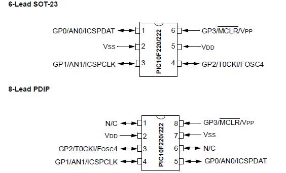
Pinout Specifications
| Program Memory Type |
Flash |
| Program Memory (KB) |
0.75 |
| CPU Speed (MIPS) |
2 |
| RAM Bytes |
23 |
| Timers |
1 x 8-bit |
| ADC |
2 ch, 8-bit |
| Temperature Range (C) |
-40 to 125 |
| Operating Voltage Range (V) |
2 to 5.5 |
| Pin Count |
6 |
Absolute Maximum Ratings(†)
Ambient temperature under bias..............................-40°C to +125°C
Storage temperature ................................................65°C to +150°C
Voltage on VDD with respect to VSS ......................................0 to +6.5V
Voltage onMCLR with respect to VSS..................................0 to +13.5V
Voltage on all other pins with respect to VSS ..... -0.3V to (VDD + 0.3V)
Total power dissipation(1) .......................................................200 mW
Max. current out of VSS pin ........................................................80 mA
Max. current into VDD pin ..........................................................80 mA
Input clamp current, IIK (VI < 0 or VI > VDD)..........................±20 mA
Output clamp current, IOK (VO < 0 or VO > VDD) .....................±20 mA
Max. output current sunk by any I/O pin ....................................25 mA
Max. output current sourced by any I/O pin ..............................25 mA
Max. output current sourced by I/O port ....................................75 mA
Max. output current sunk by I/O port .........................................75 mA
Note 1: Power dissipation is calculated as follows: PDIS = VDD x {IDD IOH} + {(VDD VOH) x IOH} + (VOL x IOL)
†NOTICE: Stresses above those listed under "Absolute Maximum Ratings" may cause permanent damage to the
device. This is a stress rating only and functional operation of the device at those or any other conditions above
those indicated in the operation listings of this specification is not implied. Exposure to maximum rating conditions
for extended periods may affect device reliability.
DescriptionThe PIC10F222 is a low-cost, high-performance, 8-bit, fully-static Flash-based CMOS microcontroller. It employs a RISC architecture with only 33 single-word/ single-cycle instructions. All instructions are singlecycle (1 s) except for program branches, which take two cycles. The PIC10F222 delivers performance in an order of magnitude higher than their competitors in the same price category. The 12-bit wide instructions are highly symmetrical, resulting in a typical 2:1 code compression over other 8-bit microcontrollers in its class. The easy-to-use and easy to remember instruction set reduces development time significantly. The PIC10F222 are also equipped with special features that reduce system cost and power requirements.

 PIC10F222 Data Sheet


