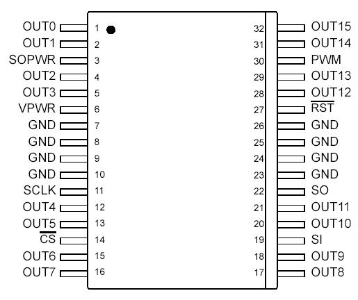
Features: • Designed to Operate 5.0 V VPWR 27 V• 24-Bit SPI for Control and Fault Reporting, 3.3 V/5.0 V Compatible• Outputs Are Current Limited (0.9 A to 2.5 A) to Drive Incandescent Lamps• Output Voltage Clamp of +50 V During Inductive Switching• On/Off Control of...
PC33996EK_R2: Features: • Designed to Operate 5.0 V VPWR 27 V• 24-Bit SPI for Control and Fault Reporting, 3.3 V/5.0 V Compatible• Outputs Are Current Limited (0.9 A to 2.5 A) to Drive Incande...
SeekIC Buyer Protection PLUS - newly updated for 2013!
268 Transactions
All payment methods are secure and covered by SeekIC Buyer Protection PLUS.
Rating | Symbol | Value | Unit |
VPWR Supply Voltage (Note 1) | VPWR | -1.5 to 50 | V |
SPI Interface Logic Supply Voltage (Note 1) | SOPWR | -0.3 to 7.0 | V |
SPI Interface Logic Input Voltage (CS, PWM, SI, SO, SCLK, RST, PWMn) (Note 1) |
VIN | -0.3 to 7.0 | V |
Output Drain Voltage | VDS | -0.3 to 45 | V |
Frequency of SPI Operation (Note 2) | fSPI | 6.0 | MHz |
Output Clamp Energy (Note 3) | ECLAMP | 50 | mJ |
ESD Voltage (Note 4) Human Body Model (Note 5) Machine Model (Note 6) |
VESD1 VESD2 |
±2000 ±200 |
V |
Storage Temperature | TSTG | -55 to 150 | °C |
Operating Case Temperature | TC | -40 to 125 | °C |
Operating Junction Temperature | TJ | -40 to 150 | °C |
Power Dissipation (TA = 25°C) (Note 7) | PD | 1.5 | W |
Lead Soldering Temperature (Note 8) | TSOLDER | 260 | °C |
Thermal Resistance Junction-to-Ambient (Note 9) Junction-to-Case (Note 10) Junction-to-Board |
RJA RJC RJB |
75 8.0 1.2 |
°C/W |
Notes
1. Exceeding these limits may cause malfunction or permanent damage to the device.
2. This parameter is guaranteed by design but not production tested.
3. Maximum output clamp energy capability at 150°C junction temperature using single nonrepetitive pulse method.
4. ESD data available upon request.
5. ESD1 testing is performed in accordance with the Human Body Model (CZAP = 100 pF, RZAP = 1500 Ω).
6. ESD2 testing is performed in accordance with the Machine Model (CZAP = 200 pF, RZAP = 0 Ω).
7. Maximum power dissipation with no heat sink used.
8. Lead soldering temperature limit is for 10 seconds maximum duration. Not designed for immersion soldering. Exceeding these limits may cause malfunction or permanent damage to the device.
9. Tested per JEDEC test JESD52-2 (single-layer PWB).
10. Tested per JEDEC test JESD51-8 (two-layer PWB).
The 33996 is a 16-output low-side switch with a 24-bit serial input control. PC33996EK_R2 is designed for a variety of applications including inductive, incandescent, and LED loads. The Serial Peripheral Interface (SPI) PC33996EK_R2 provides both input control and diagnostic readout. A Pulse Width Modulation (PWM) control input is provided for pulse width modulation of multiple outputs at the same duty cycle. A dedicated reset input provides the ability to clear all internal registers and turn all outputs off.
The 33996 directly interfaces with microcontrollers and is compatible with both 3.3 V and 5.0 V CMOS logic levels. The 33996, in effect, serves as a bus expander and buffer with fault management features that reduce the MCU's fault management burden.