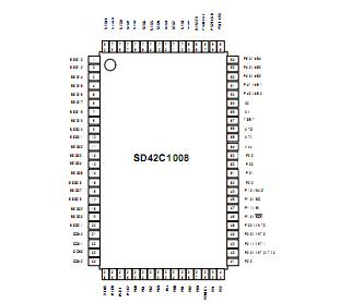
Features: Memory mapped I/OProgram memory : 8192 x 10bitsData memory : 512 x 4bitsInstructions- Various bit manipulation- 8-bit data operation- 7-bit relative branch- 1 byte absolute callInstruction cycle times - Main ( XI = 4.19MHz ) . 15.3 us ( XI/64 = 65.5KHz ) . 1.91 us ( XI/8 = 524.0KHz ) . 0...
P1008: Features: Memory mapped I/OProgram memory : 8192 x 10bitsData memory : 512 x 4bitsInstructions- Various bit manipulation- 8-bit data operation- 7-bit relative branch- 1 byte absolute callInstruction...
SeekIC Buyer Protection PLUS - newly updated for 2013!
268 Transactions
All payment methods are secure and covered by SeekIC Buyer Protection PLUS.
Memory mapped I/O
Program memory : 8192 x 10bits
Data memory : 512 x 4bits
Instructions
- Various bit manipulation
- 8-bit data operation
- 7-bit relative branch
- 1 byte absolute call
Instruction cycle times
- Main ( XI = 4.19MHz )
. 15.3 us ( XI/64 = 65.5KHz )
. 1.91 us ( XI/8 = 524.0KHz )
. 0.95 us ( XI/4 = 1.05MHz )
- Sub ( XTI = 32.768KHz )
. 122 us ( XTI/4 = 8.19KHz )
- Falling edge operation
4 Register Bank
General register : 8 x 4-bit respectively
Accumulator
- Bit Accumulator (CY), 4 bit Accumulator (A),
8 bit Accumulator (XA)
Multiple vectored interrupt source
- External interrupt : 4
- Internal interrupt : 4
Watch timer
- fast mode : 3.91 msec
- normal mode : 0.5 sec
- buzzer output : 1, 2, 4 KHz
Basic interval timer
- 8 kinds of period
- Used stabilization wait timer to wake up Stop mode
One 8-bit timer / event counter
8-bit serial communication interface
- External / Internal clock selection
- Mode : Transmit `Receive
Receive only
Clock continuous
LCD controller/driver
- selectable number of segments ;
20/24/28/32 segment (4/8/12 lines can
be specified as bit ports)
- Display mode selection
` Static
` 1/2 duty (1/2 bias)
` 1/3 duty (1/2 bias)
` 1/3 duty (1/3 bias)
` 1/4 duty (1/3 bias)
Key scan
- 4, 6, 8 Pins Selectable : Port 4, 5
- Falling edge operation
64 I/O Pins
- LCD driver output pins : 36
. Segment ouput pins : 20
. Segment CMOS output pins : 12
. Common ounput pins : 4
- CMOS input/output pins : 32
Power saving mode
- STOP : Main clock, CPU clock stop
- STBY : Only CPU clock stop
Main clock operation