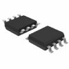
NTMD6N02R2

MOSFET 20V 6A N-Channel

product image

NTMD6N02R2 Picture
SeekIC No. : 00164547 Detail

NTMD6N02R2: MOSFET 20V 6A N-Channel

floor Price/Ceiling Price

Part Number:
NTMD6N02R2
Mfg:
ON Semiconductor
Supply Ability:
5000

Price Break

  • Qty
  • 1~5000
  • Unit Price
  • Negotiable
  • Processing time
  • 15 Days
Total Cost: $ 0.00

SeekIC Buyer Protection PLUS - newly updated for 2013!

  • Escrow Protection.
  • Guaranteed refunds.
  • Secure payments.
  • Learn more >>

Month Sales

268 Transactions

Rating

evaluate  (4.8 stars)

Upload time: 2024/12/17

Payment Methods

All payment methods are secure and covered by SeekIC Buyer Protection PLUS.

Notice: When you place an order, your payment is made to SeekIC and not to your seller. SeekIC only pays the seller after confirming you have received your order. We will also never share your payment details with your seller.
Product Details

Quick Details

Transistor Polarity : N-Channel Drain-Source Breakdown Voltage : 20 V
Gate-Source Breakdown Voltage : +/- 12 V Continuous Drain Current : 6.5 A
Resistance Drain-Source RDS (on) : 43 mOhms at 4.5 V Configuration : Dual Dual Drain
Maximum Operating Temperature : + 150 C Mounting Style : SMD/SMT
Package / Case : SOIC-8 Narrow Packaging : Reel    

Description

Transistor Polarity : N-Channel
Mounting Style : SMD/SMT
Packaging : Reel
Maximum Operating Temperature : + 150 C
Drain-Source Breakdown Voltage : 20 V
Configuration : Dual Dual Drain
Package / Case : SOIC-8 Narrow
Gate-Source Breakdown Voltage : +/- 12 V
Continuous Drain Current : 6.5 A
Resistance Drain-Source RDS (on) : 43 mOhms at 4.5 V


Features:

• Ultra Low RDS(on)
• Higher Efficiency Extending Battery Life
• Logic Level Gate Drive
• Miniature Dual SO−8 Surface Mount Package
• Diode Exhibits High Speed, Soft Recovery
• Avalanche Energy Specified
• SO−8 Mounting Information Provided


Application

• DC−DC Converters
• Low Voltage Motor Control
• Power Management in Portable and Battery−Powered Products, for
  example, Computers, Printers, Cellular and Cordless Telephones and
  PCMCIA Cards


Pinout

  Connection Diagram


Specifications

Rating Symbol Value Unit
Drain−to−Source Voltage VDSS −30 V
Drain−to−Gate Voltage (RGS = 1.0 m) VDGR 20 V
Gate−to−Source Voltage − Continuous VGS ±12 V
Thermal Resistance −
Junction−to−Ambient (Note 1)
Total Power Dissipation @ TA = 25°C
Continuous Drain Current @ 25°C
Continuous Drain Current @ 70°C
Pulsed Drain Current (Note 4)
RJA
PD
ID
ID
IDM
62.5
2.0
6.5
5.5
50
°C/W
W
A
A
A
Thermal Resistance −
Junction−to−Ambient (Note 2)
Total Power Dissipation @ TA = 25°C
Continuous Drain Current @ 25°C
Continuous Drain Current @ 70°C
Pulsed Drain Current (Note 4)
RJA
PD
ID
ID
IDM
102
1.22
5.07
4.07
40
°C/W
W
A
A
A
Thermal Resistance −
Junction−to−Ambient (Note 3)
Total Power Dissipation @ TA = 25°C
Continuous Drain Current @ 25°C
Continuous Drain Current @ 70°C
Pulsed Drain Current (Note 4)
RJA
PD
ID
ID
IDM
172
0.73
3.92
3.14
30
°C/W
W
A
A
A
1. Mounted onto a 2, square FR−4 Board
(1, sq. 2 oz. Cu 0.06, thick single sided), t < 10 seconds.
2. Mounted onto a 2, square FR−4 Board
(1, sq. 2 oz. Cu 0.06, thick single sided), t = steady state.
3. Minimum FR−4 or G−10 PCB, t = steady state.
4. Pulse Test: Pulse Width = 10 s, Duty Cycle = 2%.


Customers Who Bought This Item Also Bought

Margin,quality,low-cost products with low minimum orders. Secure your online payments with SeekIC Buyer Protection.
Cables, Wires
Optoelectronics
Undefined Category
Test Equipment
Isolators
Circuit Protection
View more