Features: ` Hardware as A1 with additional features:
Automatic NICAM-FM switching
Demodulator Short Programming
Automatic Standard Detection
` Hardware as A2 with additional features:
Automatic Volume Correction (AVC)
Subwoofer Output
improved Automatic Standard Detection
extended Short Programming Mode
automatic reset and selection of identification for Demodulator Short Programming|
ApplicationAll ground pins should be connected to one low-resis-tive ground plane.
All supply pins should be connected separately with short and low-resistive lines to the power supply.
Decoupling capacitors from DVSUP to DVSS, AVSUP to AVSS, and AHVSUP to AHVSS are recommended as closely as possible to these pins. Decoupling of DVSUP and DVSS is most important. We recommend using more than one capacitor. By choosing different values, the frequency range of active decoupling can be extended. In our application boards we use: 220 pF, 470 pF, 1.5 nF, and 10F. The capacitor with the low-est value should be placed nearest to the DVSUP and DVSS pins.
The ASG pins should be connected as closely as pos-sible to the MSP to ground. If they are lead with the SCART input lines as shielding line, they should NOT be connected to ground at the SCART connector.
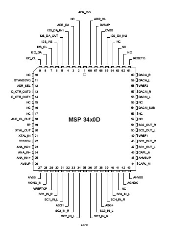
Pinout Specifications
|
Symbol |
Parameter |
Pin Name |
Min. |
Max. |
Unit |
|
TA |
Ambient Operating Temperature |
|
0 |
70 |
|
|
TS |
Storage Temperature |
|
40 |
125 |
|
|
VSUP1 |
First Supply Voltage |
AHVSUP |
0.3
|
9.0 |
V |
|
VSUP2 |
Second Supply Voltage |
DVSUP |
0.3 |
6.0 |
V |
|
VSUP3 |
Third Supply Voltage |
AVSUP |
0.3 |
6.0 |
V |
|
dVSUP23 |
Voltage between AVSUP
and DVSUP |
AVSUP,DVSUP |
0.5 |
0.5 |
V |
|
PTOT |
Package Power Dissipation
PSDIP64
PSDIP52
PQFP80
PLQFP64
PMQFP44 |
AHVSUP,
DVSUP,
AVSUP |
|
1200
1300
1200
1000
9601) |
mW
mW
mW
mW
mW |
|
VIdig |
Input Voltage, all Digital Inputs |
|
0.3
|
VSUP2+ 0.3 |
V |
|
IIdig |
Input Current, all Digital Pins |
|
20
|
+20 |
mA2) |
|
VIana |
Input Voltage, all Analog Inputs |
SCn_IN_s,MONO_IN3) |
0.3
|
VSUP2+ 0.3 |
V |
|
IIana |
Input Current, all Analog Inputs |
SCn_IN_s,MONO_IN3)
|
5
|
+5 |
mA2) |
|
IOana |
Output Current, all SCART Outputs |
SC1_OUT_s3)
|
4) 5)
, |
4) 5)
, |
|
|
IOana |
Output Current, all Analog Outputs
except SCART Outputs |
DACM_s3) |
4) |
4) |
|
|
ICana |
Output Current, other pins
connected to capacitors |
CAPL_M3), AGNDC |
4) |
4) |
|
1)PLQFP64: 65 °C
2)positive value means current flowing into the circuit
3)"n" means "1", "2", "3", or "4", "s" means "L" or "R", "p" means "M" or "A"
4)The analog outputs are short circuit proof with respect to First Supply Voltage and ground.
5)Total chip power dissipation must not exceed absolute maximum rating.
Stresses beyond those listed in the "Absolute Maximum Ratings" may cause permanent damage to the device. This
is a stress rating only. Functional operation of the device at these or any other conditions beyond those indicated in
the "Recommended Operating Conditions/Characteristics" of this specification is not implied. Exposure to absolute
maximum ratings conditions for extended periods may affect device reliability.

 MSP34x0D Data Sheet


