MBM29LV001TC-55

Features: • Single 3.0 V read, program, and erase Minimizes system level power requirements• Compatible with JEDEC-standard commands Uses same software commands as E2PROMs• Compatible with JEDEC-standard world-wide pinouts 32-pin TSOP(I) (Package suffix: PFTN Normal Bend Type, P...

product image

MBM29LV001TC-55 Picture
SeekIC No. : 004414132 Detail

MBM29LV001TC-55: Features: • Single 3.0 V read, program, and erase Minimizes system level power requirements• Compatible with JEDEC-standard commands Uses same software commands as E2PROMs• Compati...

floor Price/Ceiling Price

Part Number:
MBM29LV001TC-55
Supply Ability:
5000

Price Break

  • Qty
  • 1~5000
  • Unit Price
  • Negotiable
  • Processing time
  • 15 Days
Total Cost: $ 0.00

SeekIC Buyer Protection PLUS - newly updated for 2013!

  • Escrow Protection.
  • Guaranteed refunds.
  • Secure payments.
  • Learn more >>

Month Sales

268 Transactions

Rating

evaluate  (4.8 stars)

Upload time: 2024/11/27

Payment Methods

All payment methods are secure and covered by SeekIC Buyer Protection PLUS.

Notice: When you place an order, your payment is made to SeekIC and not to your seller. SeekIC only pays the seller after confirming you have received your order. We will also never share your payment details with your seller.
Product Details

Description


Features:

• Single 3.0 V read, program, and erase
   Minimizes system level power requirements
• Compatible with JEDEC-standard commands
   Uses same software commands as E2PROMs
• Compatible with JEDEC-standard world-wide pinouts
   32-pin TSOP(I) (Package suffix: PFTN Normal Bend Type, PFTR Reversed Bend Type)
   32-pin PLCC (Package suffix: PD)
• Minimum 100,000 program/erase cycles
• High performance
   55 ns maximum access time
• Sector erase architecture
   One 8K byte, two 4K bytes, and seven 16K bytes
   Any combination of sectors can be concurrently erased. Also supports full chip erase
• Boot Code Sector Architecture
   T = Top sector
   B = Bottom sector
• Embedded EraseTM Algorithms
   Automatically pre-programs and erases the chip or any sector
• Embedded ProgramTM Algorithms
   Automatically writes and verifies data at specified address
Data Polling and Toggle Bit feature for detection of program or erase cycle completion
• Hardware RESET pin
   Resets internal state machine to the read mode
• Automatic sleep mode
   When addresses remain stable, automatically switch themselves to low power mode
• Low Vcc write inhibit 2.5 V
• Erase Suspend/Resume
   Suspends the erase operation to allow a read data in another sector within the same device
• Sector protection
   Hardware method disables any combination of sectors from program or erase operations
• Sector Protection Set function by Extended sector protection command
• Temporary sector unprotection
   Temporary sector unprotection via the RESET pin


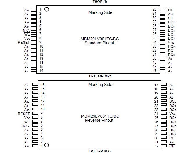
Pinout

  Connection Diagram


Specifications

Storage Temperature ..........................................................................................55°C to +125°C
Ambient Temperature with Power Applied .............................................................40°C to +85°C
Voltage with respect to Ground All pins except A9, OE and RESET (Note 1) .......0.5 V to VCC+0.5 V
VCC (Note 1) .............................................................................................................0.5 V to +5.5 V
A9, OE, and RESET (Note 2) ....................................................................................0.5 V to +13.0 V


Notes: 1. Minimum DC voltage on input or I/O pins are 0.5 V. During voltage transitions, inputs may negative    overshoot VSS to 2.0 V for periods of up to 20 ns. Maximum DC voltage on output and I/O pins are Vcc +0.5 V. During voltage transitions, outputs may positive overshoot to VCC +2.0 V for periods of up to 20 ns.

2. Minimum DC input voltage on A9, OE and RESET pins are 0.5 V. During voltage transitions, A9, OE and RESET pins may negative overshoot VSS to 2.0 V for periods of up to 20 ns. Maximum DC input voltage on A9, OE and RESET pins are +13.0 V which may positive overshoot to 14.0 V for periods of up to 20 ns. Voltage difference between input voltage and supply voltage (VIN Vcc) do not exceed 9 V.

WARNING: Semiconductor devices can be permanently damaged by application of stress (voltage, current, temperature, etc.) in excess of absolute maximum ratings. Do not exceed these ratings.


Description

The MBM29LV001TC-55 have two control functions which must be satisfied in order to obtain data at the outputs. CE is the power control and should be used for a device selection. OE is the output control and should be used to gate data to the output pins if a device is selected.

Address access time (tAcc) is equal to the delay from stable addresses to valid output data. MBM29LV001TC-55 enable access time (tCE) is the delay from stable addresses and stable CE to valid data at the output pins. The output enable access time is the delay from the falling edge of OE to valid data at the output pins. (Assuming the addresses have been stable for at least tAcc-tOE time.) When reading out a data without changing addresses after power-up, it is necessary to input hardware reset or change CE pin from "H" or "L"


Customers Who Bought This Item Also Bought

Margin,quality,low-cost products with low minimum orders. Secure your online payments with SeekIC Buyer Protection.
Optoelectronics
Audio Products
Power Supplies - External/Internal (Off-Board)
Tapes, Adhesives
803
Static Control, ESD, Clean Room Products
View more