Features: .HIGH SPEED.fMAX = 60 MHz (TYP.) AT VCC = 5V COMPATIBLE WITH TTL OUTPUTS.VIH = 2 V (MIN.) AT VIL = 0.8V (MAX) LOWPOWER DISSIPATION.ICC = 4 mA (MAX) AT TA = 25 oC OUTPUT DRIVE CAPABILITY.15 LSTTL LOADS SYMMETRICAL OUTPUT IMPEDANCE.zIOHz = IOL = 6 mA (mIN.) BALANCEDPROPAGATION DELAYS.tPLH ...
M74HCT651/652: Features: .HIGH SPEED.fMAX = 60 MHz (TYP.) AT VCC = 5V COMPATIBLE WITH TTL OUTPUTS.VIH = 2 V (MIN.) AT VIL = 0.8V (MAX) LOWPOWER DISSIPATION.ICC = 4 mA (MAX) AT TA = 25 oC OUTPUT DRIVE CAPABILITY.15...
SeekIC Buyer Protection PLUS - newly updated for 2013!
268 Transactions
All payment methods are secure and covered by SeekIC Buyer Protection PLUS.
Symbol | Parameter |
Value |
Unit |
VCC | Supply Voltage |
-0.5 to +7 |
V |
VI | DC Input Voltage |
-0.5 to VCC + 0.5 |
V |
VO | DC Output Voltage |
-0.5 to VCC + 0.5 |
V |
IIK | DC Input Diode Current |
± 20 |
mA |
IOK | DC Output Diode Current |
± 20 |
mA |
IO | DC Output Source Sink Current Per Output Pin |
± 35 |
mA |
ICC or IGND | DC VCC or Ground Current |
± 70 |
mA |
PD | Power Dissipation |
500 (*) |
mW |
Tstg | Storage Temperature |
-65 to +150 |
oC |
TL | Lead Temperature (10 sec) |
300 |
oC |
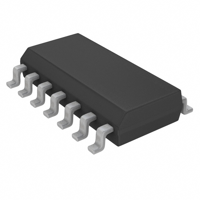
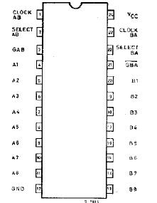
M74HCT651/652 are high speed CMOS OCTAL BUS TRANSCEIVERS AND REGISTERS (3-STATE), fabricated in silicon gate C2MOS technology. They have the same high speed performance of LSTTL combined with true CMOS low power consumption. The M74HCT651/652 consist of bus transceiver circuits, D-type flip-flops, and control circuitry arranged for multiplexed transmission of data directly from the input bus or from the internal storage registers. Enable GAB and GBA are provided to control the transceiver functions. Select AB and Select BA control pins are provided to select whether real-time or stored data is transfered. A low input level of M74HCT651/652 selects real-time data, and a high selects stored data. Data on the A or B bus, or both, can be stored in the internal D flip-flops by low-to-high transitions at the appropriate clock pins (CLOCK AB or CLOCK BA) regardless of the select or enable control pins. When select AB and select BAare in the real-time transfer mode, it is also possible to store data without using the internal D-type flip-flops by simultaneously enabling GAB and GBA. In this configuration each output reinforces its input. Thus, when all other data sources to the two sets of bus linesare at high impedance, each set ofbus lines will remain at its last state. All inputs of M74HCT651/652 are equipped with protection circuits against static discharge and transient excess voltage.This integrated circuit has input and output characteristics that are fully compatible with 54/74 LSTTL logic families.
M54/74HCT devices are designed to directly interface HSCMOS systems with TTL and NMOS components. They are also plug in replacements for LSTTL devices giving a reduction of power consumption.