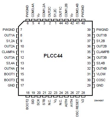
PinoutSpecifications Symbol Parameter Value Unit VP Power Supply Voltage 30 V VS Logic Supply Voltage 7 V Vin Logic Input Voltage -0.3 toVS+0.3 V ILOW Low Side DMOS max DC Current 1 A IHIGH High Side DMOS max DC Current 1 ...
L6285: PinoutSpecifications Symbol Parameter Value Unit VP Power Supply Voltage 30 V VS Logic Supply Voltage 7 V Vin Logic Input Voltage -0.3 toVS+0.3 ...
SeekIC Buyer Protection PLUS - newly updated for 2013!
268 Transactions
All payment methods are secure and covered by SeekIC Buyer Protection PLUS.
Symbol |
Parameter |
Value |
Unit |
VP |
Power Supply Voltage |
30 |
V |
VS |
Logic Supply Voltage |
7 |
V |
Vin |
Logic Input Voltage |
-0.3 toVS+0.3 |
V |
ILOW |
Low Side DMOS max DC Current |
1 |
A |
IHIGH |
High Side DMOS max DC Current |
1 |
A |
IpLOW |
Low Side DMOS max Peak Current (1ms On; 50ms OFF) |
2 |
A |
IpHIGH |
High Side DMOS max Peak Current (1ms On; 50ms OFF) |
2 |
A |
Vbout |
Max Output Voltage of Stepper Motor Driver (transientrcirculation) |
60 |
V |
Vsense1;2 |
Max Voltage ON Vsense (CHA/CHB) |
-1 to 2 |
V |
Vsense 3 |
Max Voltage ON Vsense (CHC) |
-1 to 2 |
V |
IfdDC |
Max DC Current of Forward Diode (DMOS Source Drain Diode) |
1 |
A |
Ifdpk |
Max Peak Current of Forward Diode (DMOS Source DrainDiode) (1ms On;50ms OFF) |
2 |
A |
Ptot |
Total Power Dissipation (Tpins = 90°C) With minimized dissipating copper area (Tamb= 70°C) |
5 1.6 |
W W |
Top |
Operating Temperature Range |
0 to 150 |
°C |
Tstg |
Storage Temperature Range |
-40 to 150 |
°C |
This Combo Motor Driver uses large scale integration to incorporate several functions into the same chip. 1) Two unipolar stepper motor driver 2) A full bridge DC motor driver 3) Serial microprocesor interface The power output stages are DMOS and the input can be interfaced to a CMOS Microprocessor logic.
The phase current in the unipolar stepper motor windings is controlled by two external sensing resistors in fixed frequency chopping mode. The L6285 provides clocks each other 180° out of phase to the two stepper motor driver in order to avoid symultaneous current peaks. For the DC motor driver is used a bridge; the RMS voltage to supply this motor is fixed by asimple PWMopen loop. The 3 motors are controlled by the micro through 4 latches of 4 bit each.
The loading of these registers is in serial mode. The L6285 operates at 5V supply for the logic and at 24V supply for the power stages. The packages are SDIP42 and PLCC44 with 6 pins devoted to ground and to sink out the heat produced by power dissipation.