Collector- Emitter Voltage VCEO Max
: 600 V
Maximum Operating Temperature
: + 150 C
Packaging
: Tube
Configuration
: Single
Maximum Gate Emitter Voltage
: +/- 20 V
Gate-Emitter Leakage Current
: +/- 250 nA
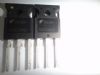
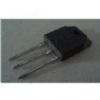
Package / Case
: TO-247-3
Collector-Emitter Saturation Voltage
: 1.6 V
Power Dissipation
: 104 W
Continuous Collector Current at 25 C
: 27 A
Features: • 27A, 600V, TC = 25
• 600V Switching SOA Capability
• Typical Fall Time. . . . . . . . . . . . . . . . 112ns at TJ = 150
• Short Circuit Rating
• Low Conduction LossPinout SpecificationsCollector to Emitter Voltage . . . . . . . . . . . . . . . . . . . . . . . . . . . . . . . . . . . . . . . . .BVCES 600 V
Collector Current Continuous. . . . . . . . . . . . . . . . . . . . . . . . . . . . . . . . . . . . . . . . . IC25 27 A
At TC = 110 . . . . . . . . . . . . . . . . . . . . . . . . . . . . . . . . . . . . . . . . . . . . . . . . . . . . IC110 12 A
Collector Current Pulsed (Note 1) . . . . . . . . . . . . . . . . . . . . . . . . . . . . . . . . . . . . . ICM 110 A
Gate to Emitter Voltage Continuous. . . . . . . . . . . . . . . . . . . . . . . . . . . . . . . . . . . VGES ±20 V
Gate to Emitter Voltage Pulsed . . . . . . . . . . . . . . . . . . . . . . . . . . . . . . . . . . . . . .VGEM ±30 V
Switching Safe Operating Area at TJ = 150 (Figure 2) . . . . . . . . . . . . . . .SSOA 96A at 600V
Maximum Power Dissipation . . . . . . . . . . . . . . . . . . . . . . . . . . . . . . . . . . . . . . . . . . PD 104 W
Linear Derating Factor . . . . . . . . . . . . . . . . . . . . . . . . . . . . . . . . . . . . . . . . . . . . . . . 0.83 W/
Reverse Voltage Avalanche Energy . . . . . . . . . . . . . . . . . . . . . . . . . . . . . . . . . . . EARV 100 mJ
Operating and Storage Temperature . . . . . . . . . . . . . . . . . . . . . . . . . . . TJ, TSTG -55 to 150
Maximum Temperature for Soldering
Leads at 0.063in (1.6mm) from Case for 10s. . . . . . . . . . . . . . . . . . . . . . . . . . . . . . . TL 300
Package Body for 10s, see Tech Brief 334. . . . . . . . . . . . . . . . . . . . . . . . . . . . . . . . Tpkg 260
Short Circuit Withstand Time (Note 2) at VGE = 12V. . . . . . . . . . . . . . . . . . . . . . . . . . .tSC 5 µs
Short Circuit Withstand Time (Note 2) at VGE = 10V. . . . . . . . . . . . . . . . . . . . . . . . . .tSC 10 µsDescriptionThis family of MOS gated high voltage switching devices combine the best features of MOSFETs and bipolar transistors. These HGTG12N60B3 devices have the high input impedance of a MOSFET and the low on-state conduction loss of a bipolar transistor. The much lower on-state voltage drop varies only moderately between 25 and 150.
The HGTG12N60B3 IGBT is ideal for many high voltage switching applications operating at moderate frequencies where low conduction losses are essential, such as: AC and DC motor controls, power supplies and drivers for solenoids, relays and contactors.Formerly developmental type TA49171.
 HGTG12N60B3 Data Sheet