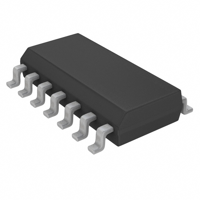
Features: ` 16 STAGE BINARI COUNTER` LOWSYMMETRICAL OUTPUT RESISTANCE, TYPICALLY 100 OHM AT VDD = 15V` OSCILLATOR FREQUENCY RANGE : DC TO 100kHz` AUTO OR MASTER RESET DISABLES OSCILLATOR` DURINGRESET TO REDUCE POWER DISSIPATION` OPERATES WITH VERY SLOW CLOCK RISE AND FALL TIMES` BUILT-IN LOW-POWER...
HCF4541B: Features: ` 16 STAGE BINARI COUNTER` LOWSYMMETRICAL OUTPUT RESISTANCE, TYPICALLY 100 OHM AT VDD = 15V` OSCILLATOR FREQUENCY RANGE : DC TO 100kHz` AUTO OR MASTER RESET DISABLES OSCILLATOR` DURINGRESE...
SeekIC Buyer Protection PLUS - newly updated for 2013!
268 Transactions
All payment methods are secure and covered by SeekIC Buyer Protection PLUS.
Symbol |
Parameter |
Value |
Unit |
VDD* | Supply Voltage : HCC Types HCF Types |
0.5 to + 20 0.5 to + 18 |
V V |
VI |
Input Voltage |
0.5 to VDD + 0.5 |
V |
II |
DC Input Current (any one input) |
± 10 |
mA |
Ptot |
Total Power Dissipation (per package) Dissipation per Output Transistor for Top = Full Package-temperature range |
200 100 |
mW mW |
Top |
rating Temperature : HCC Types HCF Types |
55 to + 125 40 to + 85 |
|
Tstg |
Storage Temperature |
65 to + 150 |
|
The HCC/HCF4541B Programmable Timer is composed of a 16-stage binary counter, an oscillator controlled by2 external resistorsand a capacitor, an output control logic and an automatic power-on reset circuit. The HCC/HCF4541B counter varies on positive-edge clock transation and it can be cleared by the MASTER RESET input. The output from this timer is the Q or Q output from the 8th, 13th, or 16th counter stage. The choice of the stage depends on the timeselect inputs A or B (see frequency selection table). The output of HCC/HCF4541B is available in one of the twomodes that can be selected via the MODE input, pin 10 (see truth table). The output turns out as a continuous squarewave, with a frequency equal to theoscillator frequency divided by 2N. When this MODE input is logic " 1 ", when it is a logic " 0 " and after a MASTER
RESET is started, and Q output has been selected, the output goes up to a high state after 2N-1 counts. It remains in that state till another MASTER RESET pulse is apply or the mode input is a logic " 1 ". The process starts by setting the AUTO RESET input (pin 5) to logic " 0 " and switching power on. If pin 5 is set to logic " 1 ", the AUTO RESET circuit is not enabled and counting cannot start till a positive MASTERRESET pulse is applied, returning to alow level. The AUTO RESET consumes a remarkable amount of power and should not be used if lowpower operation is wanted.
The frequency of the oscillator depends on the RC network. It can be calculated using the following formula:
f = 1
2.3 RTC CTC
where f is between 1 kHz and 100 kHz and RS 10 k and 9 2 RTC