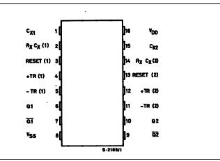
PinoutSpecifications Symbol Parameter Value Unit VDD Supply Voltage -0.5 to +22 V VI DC Input Voltage -0.5 to VDD + 0.5 V II DC Input Current ± 10 mA PD Power Dissipation per Package 200 mW Power Dissipation per Output Transistor 100 mW Top Operating Tem...
HCF4098BEY_1164537: PinoutSpecifications Symbol Parameter Value Unit VDD Supply Voltage -0.5 to +22 V VI DC Input Voltage -0.5 to VDD + 0.5 V II DC Input Current ± 10 mA PD Power Dissipa...
SeekIC Buyer Protection PLUS - newly updated for 2013!
268 Transactions
All payment methods are secure and covered by SeekIC Buyer Protection PLUS.
Symbol | Parameter | Value | Unit |
VDD | Supply Voltage | -0.5 to +22 | V |
VI | DC Input Voltage | -0.5 to VDD + 0.5 | V |
II | DC Input Current | ± 10 | mA |
PD | Power Dissipation per Package | 200 | mW |
Power Dissipation per Output Transistor | 100 | mW | |
Top | Operating Temperature | -55 to +125 | |
Tstg | Storage Temperature | -65 to +150 |
Absolute Maximum Ratings are those values beyond which damage to the device may occur. Functional operation nder these conditions is not implied.
All voltage values are referred to VSS pin voltage.
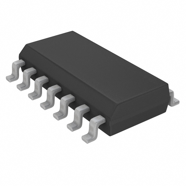
The HCF4098B is a monolithic integrated circuit fabricated in Metal Oxide Semiconductor technology available in DIP and SOP packages. The HCF4098B dual precision monostable multivibrator provides stable retriggerable/resettable one-shot operation for any fixed voltage timing application. An external resistor (RX) and an external capacitor (CX) control the timing for the circuit. Adjustment of RX and CX provides a wide range of output pulse widths from the Q and Q terminals. The time delay from trigger input to output transition (trigger propagation delay) and the time delay from reset input to output transition (reset propagation delay) and the time delay from reset input to output transition (reset propagation delay) are independent of RX and CX. Leading edge triggering (+TR) and trailing edge triggering (-TR) inputs are provided for triggering from either edge of an input pulse. An unused +TR input should be tied to VSS. An unused -TR input should be tied to VDD . A RESET (on low level) is provided for immediate termination of the output pulse or to prevent output pulses when power is turned on.