Features: · CLOCK POLARITY CONTROL· Q AND Q OUTPUTS· COMMON CLOCK· LOW POWER TTL COMPATIBLE· STANDARDIZED SYMMETRICAL OUTPUT CHARACTERISTICS· QUIESCENT CURRENT SPECIFIED UP TO 20V· 5V, 10V AND 15V PARAMETRIC RATINGS· INPUT LEAKAGE CURRENT II= 100nA (MAX) AT VDD = 18V TA = 25°C· 100% TESTED FOR QUI...
HCF4042B: Features: · CLOCK POLARITY CONTROL· Q AND Q OUTPUTS· COMMON CLOCK· LOW POWER TTL COMPATIBLE· STANDARDIZED SYMMETRICAL OUTPUT CHARACTERISTICS· QUIESCENT CURRENT SPECIFIED UP TO 20V· 5V, 10V AND 15V P...
SeekIC Buyer Protection PLUS - newly updated for 2013!
268 Transactions
All payment methods are secure and covered by SeekIC Buyer Protection PLUS.
· CLOCK POLARITY CONTROL
· Q AND Q OUTPUTS
· COMMON CLOCK
· LOW POWER TTL COMPATIBLE
· STANDARDIZED SYMMETRICAL OUTPUT CHARACTERISTICS
· QUIESCENT CURRENT SPECIFIED UP TO 20V
· 5V, 10V AND 15V PARAMETRIC RATINGS
· INPUT LEAKAGE CURRENT II = 100nA (MAX) AT VDD = 18V TA = 25°C
· 100% TESTED FOR QUIESCENT CURRENT
· MEETS ALL REQUIREMENTS OF JEDEC JESD13B " STANDARD SPECIFICATIONS FOR DESCRIPTION OF B SERIES CMOS DEVICES"
Symbol | Parameter | Value | Unit |
VDD | Supply Voltage | -0.5 to +22 | V |
VI | DC Input Voltage | -0.5 to VDD + 0.5 | V |
II | DC Input Current | ± 10 | mV |
PD | Power Dissipation per Package | 200 | mW |
Power Dissipation per Output Transistor | 100 | mW | |
Top | Operating Temperature | -55 to +125 | |
Tstg | Storage Temperature | -65 to +150 |
Absolute Maximum Ratings are those values beyond which damage to the device may occur. Functional operation under these conditions is not implied.
All voltage values are referred to VSS pin voltage.
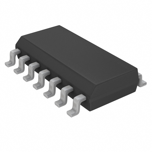
The HCF4042B is a monolithic integrated circuit fabricated in Metal Oxide Semiconductor technology available in DIP and SOP packages.
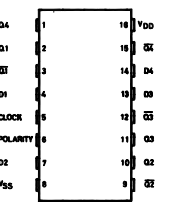
The HCF4042B types contains four latch circuit,each strobes by a common clock. Complementarybuffered outputs are available from each circuit. The impedance of the n and p channel output devices is balanced and all outputs are electrically identical.
Information present at the data input of HCF4042B is transferred to outputs Q and Q during the CLOCK level which is programmed by the POLARITY input. For POLARITY = 0 the transfer occurs during the 0 CLOCK level and for POLARITY = 1 the transfer occurs during the 1 CLOCK level. The outputs follow the data input providing the CLOCK and POLARITY levels defined above are present. When a CLOCK transition occurs (positive for POLARITY = 0 and negative for POLARITY = 1) the information present at the input during the CLOCK transition is retained at the outputs until an opposite CLOCK transition occurs.