Specifications Symbol Parameter Value Unit VDD* Supply Voltage :HCC Types HCF Types 0.5 to + 20 0.5 to + 18 VV Vi Input Voltage 0.5 to VDD + 0.5 V II DC Input Current (any one input) ± 10 mA Ptot Total Power Dissipation (per package)Dissipation per Output T...
HCF40161B: Specifications Symbol Parameter Value Unit VDD* Supply Voltage :HCC Types HCF Types 0.5 to + 20 0.5 to + 18 VV Vi Input Voltage 0.5 to VDD + 0.5 V II DC Input Curren...
SeekIC Buyer Protection PLUS - newly updated for 2013!
268 Transactions
All payment methods are secure and covered by SeekIC Buyer Protection PLUS.
Symbol | Parameter | Value | Unit |
VDD* | Supply Voltage :HCC Types HCF Types |
0.5 to + 20 0.5 to + 18 |
V V |
Vi | Input Voltage | 0.5 to VDD + 0.5 | V |
II | DC Input Current (any one input) | ± 10 | mA |
Ptot | Total Power Dissipation (per package) Dissipation per Output Transistor for Top = Full Package-temperature Range |
200 100 |
mW mW |
Top | Operating Temperature : HCC Types HCF Types |
55 to + 125 40 to + 85 |
°C °C |
Tstg | Storage Temperature | 65 to + 150 | °C |
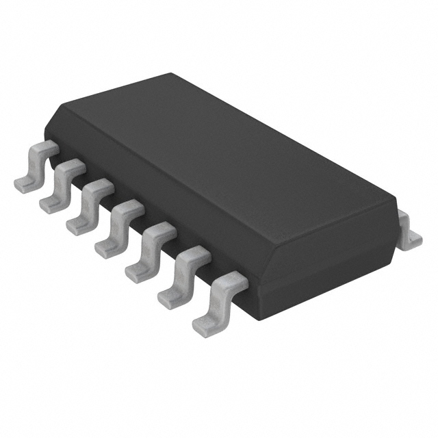
In the HCC/HCF40160B, 40161B, 40162B and 40163B series, the HCC40160B, 40161B, 40162B, 40163B (extended temperature range) and HCF40160B, 40161B, 40162B, 40163B (intermediate temperature range) are monolithic integrated circuits, available in 16-lead dual in line plastic or ceramic package and plastic micropackage.
HCC/HCF40160B, 40161B, 40162B and 40163B are 4-bit synchronous programmable counters. The CLEAR function of the HCC/HCF40162B and 40163B is synchronous and a lowon the at the clear CLEAR input sets all four outputs low on the next positive CLOCK edge. The CLEAR function of the HCC/HCF40160B and 40161B is asynchronous and a low level at the CLEAR input sets all four outputs low regardless of the state of the CLOCK, LOAD or ENABLE inputs. A low level at the LOAD input disables the counter and causes the output to agree with the set-up data after the next CLOCK pulse regardless of the conditions of theENABLE in- cascading counter for n-bit synchronour application without additional gating. Instrumental in accomplishing this function are two count-enable input and a carry output (COUT). Counting is enable when both PE and TE inputs are high. The TE input is fed forward to enable COUT. This enable output produces a positive output pulse with a duration approximately equal to the positive portion of the Q1 output. This positive overflow carry pulse can be used to enable successive cascaded stages. Logic transitions at the PE or TE inputs may occur when the clock is either high or low.