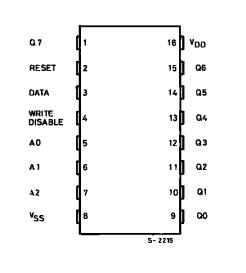
PinoutSpecifications Symbol Parameter Value Unit VDD * Supply Voltage: HCC TypesHCF Types -0.5 to +20-0.5 to +18 VV Vi Input Voltage -0.5 to VDD + 0.5 V II DC Input Current (any one input) ± 10 mA Ptot Total Power Dissipation (per package)Dissipation per Output T...
HCC4099BF_1189541: PinoutSpecifications Symbol Parameter Value Unit VDD * Supply Voltage: HCC TypesHCF Types -0.5 to +20-0.5 to +18 VV Vi Input Voltage -0.5 to VDD + 0.5 V II DC Input Curre...
SeekIC Buyer Protection PLUS - newly updated for 2013!
268 Transactions
All payment methods are secure and covered by SeekIC Buyer Protection PLUS.
Symbol | Parameter | Value | Unit |
VDD * | Supply Voltage: HCC Types HCF Types |
-0.5 to +20 -0.5 to +18 |
V |
Vi | Input Voltage | -0.5 to VDD + 0.5 | V |
II | DC Input Current (any one input) | ± 10 | mA |
Ptot | Total Power Dissipation (per package) Dissipation per Output Transistor for Top = Full Package Temperature Range |
200 100 |
mW mW |
Top | Operating Temperature: HCC Types HCF Types |
-55 to +125 -40 to +85 |
|
Tstg | Storage Temperature | -65 to +150 |
Stresses above listed under "Absolute Maximum Ratings" may cause permanent damage to the device. This is a tress rating only and functional operation of the device at these or any other conditions above those indicated in the operational sections of this specification is not implied. Exposure to absolute maximum rating conditions for external periods may affect device reliability.
* All voltage values are referred to VSS pin voltage.
The HCC/HCF4099B are monolithic integrated circuits, available in16-lead dual in-line plastic or ceramic package and plastic micro package. The HCC/HCF4099B 8-bit addressable latch is aserial-input, parallel-output storage register that can perform a variety of functions. Data are in- putted to a particular bit in the latch when that bit is addressed (by means of inputs A0, A1, A2) and when WRITE DISABLE is at a low level. When WRITE DISABLE is high, data entry is inhibited ;however, all 8 outputs can be continuously read in-dependent ofWRITE DISABLE and address inputs. A master RESET input is available, which resets all bits to a logic "0" level when RESET and WRITE DISABLE are at a high level.When RESET is at a high level, andWRITEDISABLE is at a lowlevel, the latch acts as a 1-of-8 demultiplexer ; the bit that is addressed has an active output which follows the data input, while all unaddressed bits are held to a logic "0" level.