DS14185

Features: · Replaces one 1488 and two 1489s· Conforms to EIA/TIA-232-E· 3 drivers and 5 receivers· Flow through pinout· Failsafe receiver outputs· 20-pin SOIC package· LapLink® compatible −200 kbps data rateApplication· In a typical Data Terminal Equipment (DTE) to Data Circuit-Terminati...

product image

DS14185 Picture
SeekIC No. : 004328556 Detail

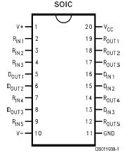
DS14185: Features: · Replaces one 1488 and two 1489s· Conforms to EIA/TIA-232-E· 3 drivers and 5 receivers· Flow through pinout· Failsafe receiver outputs· 20-pin SOIC package· LapLink® compatible −...

floor Price/Ceiling Price

Part Number:
DS14185
Supply Ability:
5000

Price Break

  • Qty
  • 1~5000
  • Unit Price
  • Negotiable
  • Processing time
  • 15 Days
Total Cost: $ 0.00

SeekIC Buyer Protection PLUS - newly updated for 2013!

  • Escrow Protection.
  • Guaranteed refunds.
  • Secure payments.
  • Learn more >>

Month Sales

268 Transactions

Rating

evaluate  (4.8 stars)

Upload time: 2024/10/20

Payment Methods

All payment methods are secure and covered by SeekIC Buyer Protection PLUS.

Notice: When you place an order, your payment is made to SeekIC and not to your seller. SeekIC only pays the seller after confirming you have received your order. We will also never share your payment details with your seller.
Product Details

Description


Features:

· Replaces one 1488 and two 1489s
· Conforms to EIA/TIA-232-E
· 3 drivers and 5 receivers
· Flow through pinout
· Failsafe receiver outputs
· 20-pin SOIC package
· LapLink® compatible −200 kbps data rate


Application

· In a typical Data Terminal Equipment (DTE) to Data Circuit-Terminating Equipment (DCE) 9-pin de-facto interface implementation, 2 data lines and 6 control lines are required. The data lines are TXD and RXD. The control lines are RTS, DTR, DSR, DCD, CTS, and RI.
· The DS14185 is a 3 x 5 Driver/Receiver and offers a single chip solutuion for this DTE interface. As shown in Figure 5, this interface allows for direct flow-thru interconnect. For a more conservative design, the user may wish to insert ground traces between the signal lines to minimize cross talk.


Pinout

  Connection Diagram


Specifications

Drivers 3
Receivers 5
Max Data Rate 0.2 Mbps
SupplyVoltage 5 Volt
OtherSupply Voltage +/-12V and 5V
Process Bipolar
ESD Rating 1500 HBM
Temperature Min 0 deg C
Temperature Max 70 deg C
JTAG1149.1 No
Function Driver/Receiver
View Using Catalog


Supply Voltage (VCC) .....................................................................+7V
Supply Voltage (V+) .....................................................................+15V
Supply Voltage (V) .....................................................................−15V
Driver Input Voltage .............................................................0V to VCC
Driver Output Voltage (Power Off) ...............................................±15V
Receiver Input Voltage ................................................................±25V
Receiver Output Voltage (ROUT) ...........................................0V to VCC
Maximum Package Power Dissipation @ +25°C M Package ..1488 mW
Derate M Package ......................................11.9 mW/°C above +25°C
Storage Temperature Range ...................................−65°C to +150°C
Lead Temperature Range (Soldering, 4 seconds) ...................+260°C
ESD Ratings (HBM, 1.5 k, 100 pF) ......................................... 1.5 kV


Description

The DS14185 is a three driver, five receiver device which conforms to the EIA/TIA-232-E standard.

The flow-through pinout facilitates simple non-crossover board layout. The DS14185 provides a one-chip solution for the common 9-pin serial RS-232 interface between data terminal and data communications equipment.


Customers Who Bought This Item Also Bought

Margin,quality,low-cost products with low minimum orders. Secure your online payments with SeekIC Buyer Protection.
Crystals and Oscillators
Isolators
Power Supplies - External/Internal (Off-Board)
Fans, Thermal Management
View more