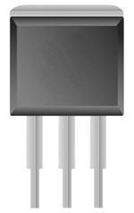
DescriptionThe BT139-800G is designed as glass passivated triac in a plastic envelope, intended for use in applications requiring high bidirectional transient and blocking voltage capability and high thermal cycling performance. Typical applications of BT139-800G include motor control, industrial ...
BT139-800G: DescriptionThe BT139-800G is designed as glass passivated triac in a plastic envelope, intended for use in applications requiring high bidirectional transient and blocking voltage capability and hig...
SeekIC Buyer Protection PLUS - newly updated for 2013!
268 Transactions
All payment methods are secure and covered by SeekIC Buyer Protection PLUS.
The BT139-800G is designed as glass passivated triac in a plastic envelope, intended for use in applications requiring high bidirectional transient and blocking voltage capability and high thermal cycling performance. Typical applications of BT139-800G include motor control, industrial and domestic lighting, heating and static switching.
Some limit ratings have been concluded into several points of BT139-800G as follow. Its repetitive peak off-state voltages would be 800V. (2)Its RMS on-state current would be 16A. (3)Its non-repetitive peak on-state current would be 140A at t=20ms and would be 150A at t=16.7ms. (4)Its I2t for fusing would be 98A2s at t=10ms. (5)Its repetitive rate of rise of on-state current after triggering would be 50A/us and it would be 10A/us for T2-G+. (6)Its peak gate current would be 2A. (7)Its peak gate voltage would be 5V. (8)Its peak gate power would be 5W. (9)Its average gate power would be 0.5W over any 20ms period. (10)Its storage temperature range would be from -40°C to 150°C. (11)Its operating junction temperature would be 125°C. It should be noted that stresses above those listed in absolute maximum ratings may cause permanent damage to device.
Also some electrical characteristics about BT139-800G are concluded as follow. (1)Its gate trigger current would be 50mA and would be 100mA for T2-G+. (2)Its latching current would be 60mA for T2+G+ and T2-G- and would be 90mA for T2+G- and for T2-G+. (3)Its holding current would be max 60mA. (4)Its on-state voltage would be typ 1.2V and max 1.6V. (5)Its gate trigger voltage would be typ 0.7V and max 1.5V at Vd=12V and would be min 0.25V and typ 0.4V at Vd=400V. (6)Its off-state leakage current would be typ 0.1mA and max 0.5mA. (7)Its critical rate of rise of off-state voltage would be min 200V/us and typ 250V/us. And so on. If you have any question or suggestion or want to know more information please contact us for details. Thank you!