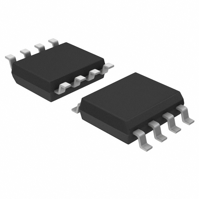
BA3714F

Features: 1) Operation possible at ultra-low voltages. (VCC = 0.8 to 4.5V)2) Minimal attached components.3) Uses dual rectified current method for excellent signal response.4) Very low current dissipation. (IQ = 0.9mA)5) When used for a tape end sensor, can also be used with mechanical auto-off.6)...

product image

BA3714F Picture
SeekIC No. : 004295504 Detail

BA3714F: Features: 1) Operation possible at ultra-low voltages. (VCC = 0.8 to 4.5V)2) Minimal attached components.3) Uses dual rectified current method for excellent signal response.4) Very low current dissi...

floor Price/Ceiling Price

Part Number:
BA3714F
Supply Ability:
5000

Price Break

  • Qty
  • 1~5000
  • Unit Price
  • Negotiable
  • Processing time
  • 15 Days
Total Cost: $ 0.00

SeekIC Buyer Protection PLUS - newly updated for 2013!

  • Escrow Protection.
  • Guaranteed refunds.
  • Secure payments.
  • Learn more >>

Month Sales

268 Transactions

Rating

evaluate  (4.8 stars)

Upload time: 2024/10/30

Payment Methods

All payment methods are secure and covered by SeekIC Buyer Protection PLUS.

Notice: When you place an order, your payment is made to SeekIC and not to your seller. SeekIC only pays the seller after confirming you have received your order. We will also never share your payment details with your seller.
Product Details

Description


Features:

1) Operation possible at ultra-low voltages. (VCC = 0.8 to 4.5V)
2) Minimal attached components.
3) Uses dual rectified current method for excellent signal response.
4) Very low current dissipation. (IQ = 0.9mA)
5) When used for a tape end sensor, can also be used
  with mechanical auto-off.
6) SOP 8-pin package allows space conservation on the board.


Application

Tape end sensors for 1.5 to 3V headphone stereos
Mute and song selection sensors


Specifications

  Connection Diagram


Description

The BA3714F is a signal sensor consisting of a sensor circuit which detects the presence of an input signal, a logic circuit which controls an output drive circuit based on the input signal, and an output drive circuit. The signal sensor circuit employs the dual-wave rectified current method for excellent response.

The outputs TE of Pin 3 and TON of Pin 5 can be respectively set by choosing appropriate values for the capacitor between Pin 7 and VCC and the capacitor between Pin 1 and ground.

Drive outputs include two systems OUT1 and OUT which are controlled by the logic block. These systems can be combined to enable a wide range of designs.


Customers Who Bought This Item Also Bought

Margin,quality,low-cost products with low minimum orders. Secure your online payments with SeekIC Buyer Protection.
Cable Assemblies
Industrial Controls, Meters
Optical Inspection Equipment
Fans, Thermal Management
Motors, Solenoids, Driver Boards/Modules
View more