Features: • 80C51 Core Architecture
• 256 Bytes of On-chip RAM
• 1K Bytes of On-chip XRAM
• 32K Bytes of On-chip Flash Memory Data Retention: 10 Years at 85°C Erase/Write Cycle: 100K
• Boot Code Section with Independent Lock Bits
• 2K Bytes of On-chip Flash for Bootloader
• In-System Programming by On-Chip Boot Program (CAN, UART) and IAP Capability
• 2K Bytes of On-chip EEPROM Erase/Write Cycle: 100K
• 14-sources 4-level Interrupts
• Three 16-bit Timers/Counters
• Full Duplex UART Compatible 80C51
• Maximum Crystal Frequency 40 MHz, in X2 Mode, 20 MHz (CPU Core, 20 MHz)
• Five Ports: 32 + 2 Digital I/O Lines
• Five-channel 16-bit PCA with: PWM (8-bit) High-speed Output Timer and Edge Capture
• Double Data Pointer
• 21-bit Watchdog Timer (7 Programmable Bits)
• A 10-bit Resolution Analog to Digital Converter (ADC) with 8 Multiplexed Inputs
• Full CAN Controller: Fully Compliant with CAN Rev2.0A and 2.0B Optimized Structure for Communication Management (Via SFR) 15 Independent Message Objects: Each Message Object Programmable on Transmission or Reception Individual Tag and Mask Filters up to 29-bit Identifier/Channel 8-byte Cyclic Data Register (FIFO)/Message Object 16-bit Status and Control Register/Message Object 16-bit Time-Stamping Register/Message Object CAN Specification 2.0 Part A or 2.0 Part B Programmable for Each Message Object Access to Message Object Control and Data Registers Via SFR Programmable Reception Buffer Length Up To 15 Message Objects Priority Management of Reception of Hits on Several Message Objects at the Same Time (Basic CAN Feature) Priority Management for Transmission Message Object Overrun Interrupt Supports: Time Triggered Communication Autobaud and Listening Mode Programmable Automatic Reply Mode 1-Mbit/s Maximum Transfer Rate at 8 MHz (1) Crystal Frequency in X2 Mode Readable Error Counters Programmable Link to On-chip Timer for Time Stamping and Network Synchronization Independent Baud Rate Prescaler Data, Remote, Error and Overload Frame Handling
• On-chip Emulation Logic (Enhanced Hook System)
• Power Saving Modes: Idle Mode Power-down ModeApplicationSoftware can take advantage of the additional data pointers to both increase speed and reduce code size, for example, block operations (copy, compare.) are well served by using one data pointer as a "source" pointer and the other one as a "destination" pointer.
Hereafter is an example of block move implementation using the two pointers and coded in assembler. The latest C compiler takes also advantage of this feature by providing enhanced algorithm libraries.
The INC instruction is a short (2 Bytes) and fast (6 machine cycle) way to manipulate the DPS bit in the AUXR1 register. However, note that the INC instruction does not directly force the DPS bit to a particular state, but simply toggles it. In simple routines, such as
the block move example, only the fact that DPS is toggled in the proper sequence matters, not its actual value. In other words, the block move routine works the same whether DPS is '0' or '1' on entry.
; ASCII block move using dual data pointers; Modifies DPTR0, DPTR1, A and PSW; Ends when encountering NULL character; Note: DPS exits opposite to the entry state unless an extra INC AUXR1 is added AUXR1EQU0A2hmove:movDPTR,#SOURCE ; address of SOURCE incAUXR1 ; switch data pointers movDPTR,#DEST ; address of DEST mv_loop:incAUXR1; switch data pointers movxA,@DPTR; get a byte from SOURCE incDPTR; increment SOURCE address incAUXR1; switch data pointers movx@DPTR,A; write the byte to DEST incDPTR; increment DEST address jnzmv_loop; check for NULL terminatorend_move:
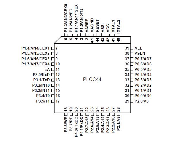
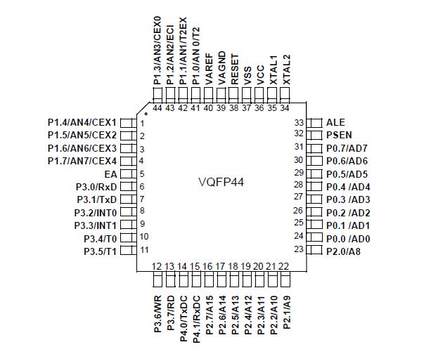
Pinout
 SpecificationsI = industrial ....................................................... -40°C to 85°C
Storage Temperature .................................... -65°C to + 150°C
Voltage on VCC from VSS .........................................-0.5V to + 6V
Voltage on Any Pin from VSS.................... ....-0.5V to VCC + 0.2 V
Power Dissipation ................................................................. 1 WDescriptionThe T89C51CC01 is the first member of the CANaryTM family of 8-bit microcontrollers dedicated to CAN network applications.
In X2 mode a maximum external clock rate of 20 MHz reaches a 300 ns cycle time.Besides the full CAN controller T89C51CC01 provides 32K Bytes of Flash memory including In-System-Programming (ISP), 2K Bytes Boot Flash Memory, 2K Bytes EEPROM and 1.2-Kbyte RAM.
Special attention is paid to the reduction of the electro-magnetic emission of T89C51CC01.

 AT89C51CC01 Data Sheet


