Features: · 2.5V, 3.0V, 3.3V and 5.0V Versions
· High Accuracy Output Voltage
· Extremely Low Quiescent Current
· Low Dropout Voltage
· Extremely Tight Load and Line Regulation
· Very Low Temperature Coefficient
· Current and Thermal Limiting
· Needs Minimum Capacitance (1mF) for Stability
· Unregulated DC Positive Transients 60V
ADDITIONAL FEATURES (ADJ ONLY)
· 1.24V to 29V Programmable Output
· Error Flag Warning of Voltage Output Dropout
· Logic Controlled Electronic Shutdown
ApplicationA 1.0 mF or greater capacitor is required between output and ground for stability at output voltages of 5V or more. At lower output voltages, more capacitance is required (2.2m or more is
recommended for 2.5V, 3.0V and 3.3V versions). Without this capacitor the part will oscillate. Most types of tantalum or aluminum electrolytic works fine here; even film types work but
are not recommended for reasons of cost. Many aluminum types have electrolytes that freeze at about -30°C, so solid tantalums are recommended for operation below -25°C. The important parameters of the capacitor are an ESR of about 5 W or less and resonant frequency above 500 kHz parameters in the value of the capacitor. The value of this capacitor may be increased without limit.
At lower values of output current, less output capacitance is required for stability. The capacitor can be reduced to 0.33 mF for currents below 10 mA or 0.1 mF for currents below 1 mA. Using the adjustable versions at voltages below 5V runs the error amplifier at lower gains so that more output capacitance is needed. For the worst-case situation of a 300mA load at 1.23V output (Output shorted to Feedback) a 3.3mF (or greater) capacitor should be used.
Unlike many other regulators, the AMS2954, will remain stable and in regulation with no load in addition to the internal voltage divider. This is especially important in CMOS RAM keep-alive applications. When setting the output voltage of the AMS2954 version with external resistors, a minimum load of 1mA is recommended.
A 1mF tantalum or aluminum electrolytic capacitor should be placed from the AMS2954/AMS2954 input to the ground if there is more than 10 inches of wire between the input and the AC filter capacitor or if a battery is used as the input.
Stray capacitance to the AMS2954 Feedback terminal can cause instability. This may especially be a problem when using a higher value of external resistors to set the output voltage. Adding a 100 pF capacitor between Output and Feedback and increasing the output capacitor to at least 3.3 mF will fix this problem.
Since the AMS2954's dropout voltage is load dependent (see curve in typical performance characteristics), the input voltage trip point (about 5V) will vary with the load current. The output
voltage trip point (approx. 4.75V) does not vary with load.
The error comparator has an open-collector output which requires an external pull-up resistor. This resistor may be returned to the output or some other supply voltage depending on system requirements. In determining a value for this resistor, note that the output is rated to sink 400mA, this sink current adds to battery drain in a low battery condition. Suggested values range from 100K to 1MW. The resistor is not required if this output is unused.
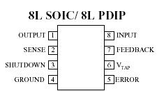
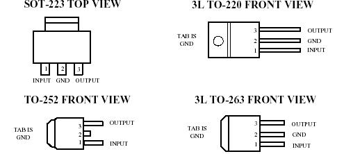
Pinout
 Specifications
Input Supply Voltage ..............................................-0.3 to +30V
SHUTDOWN Input Voltage,
Error Comparator Output
Voltage,(Note 9)
FEEDBACK Input Voltage ..........................................-1.5 to +30V
(Note 9) (Note 10)
Power Dissipation ..............................................Internally Limited
Junction Temperature ....................................................+150°C
Storage Temperature ......................................-65°C to +150°C
ESD .......................................................................................2kV
Soldering Dwell Time, Temperature
Wave............................................................... 4 seconds, 260°C
Infrared............................................................ 4 seconds, 240°C
Vapor Phase.................................................... 4 seconds, 219°C
DescriptionAMS2954 are micro power voltage regulators with very low quiescent current (typ. 75?A), and very low dropout voltage (typ.50mV at light loads and 380mV at 250mA), ideally suited for use in battery-powered systems. The quiescent current increases only slightly at dropout, thus prolonging battery life. The AMS2954 series has positive transient protection up to 60V and can survive unregulated input transient up to 20V below ground. Featuring a tight initial tolerance (typ. 0.5%), excellent load and line regulation (typ. 0.05%), and a very low output voltage temperature coefficient, the AMS2954 can be used as a low-power voltage reference. The AMS2954 is available in the 3L TO-220 package, 3L TO-263, SOT-223, TO-252 and in 8-pin plastic SOIC and DIP packages. In the 8L SOIC and PDIP packages the following additional features are offered: an error flag output warns of a low output voltage, often due to failing batteries on input; the logic-compatible shutdown input enables the regulator to be switched on and off; the device may be pin-strapped for a 2.5V, 3.0V, 3.3V or 5.0V output, or programmed from 1.24V to 29V with an external pair of resistors.

 AMS2954 Data Sheet


