Features: • Combines 74LVT245 and 74LVT574 type functions in one device
• Independent registers for A and B buses
• Multiplexed realtime and stored data
• Output capability: +64mA/32mA
• TTL input and output switching levels
• Input and output interface capability to systems at 5V supply
• Bus-hold data inputs eliminate the need for external pull-up resistors to hold unused inputs
• Live insertion/extraction permitted
• No bus current loading when output is tied to 5V bus
• Latch-up protection exceeds 500mA per JEDEC Std 17
• Power-up 3-State
• Power-up reset
• ESD protection exceeds 2000V per MIL STD 883 Method 3015 and 200V per Machine ModelPinout Specifications
| SYMBOL |
PARAMETER |
CONDITIONS |
RATING |
UNIT |
| VCC |
DC supply voltage |
|
0.5 to +4.6 |
V |
| IIK |
DC input diode current |
VI < 0 |
50 |
mA |
| VI |
DC input voltage3 |
|
0.5 to +7.0 |
V |
| IOK |
DC output diode current |
VO < 0 |
50 |
mA |
| VOUT |
DC output voltage3 |
Output in Off or High state |
0.5 to +7.0 |
V |
| IO Output in Low state 128 IOUT mA |
DC output current |
Output in Low state |
128 |
mA |
| Output in High state |
-64 |
| Tstg |
storage temperature |
|
65 to 150 |
°C |
NOTES:
1. Stresses beyond those listed may cause permanent damage to the device. These are stress ratings only and functional operation of the device at these or any other conditions beyond those indicated under "recommended operating conditions" is not implied. Exposure to absolute-maximum-rated conditions for extended periods may affect device reliability.
2. The performance capability of a high-performance integrated circuit in conjunction with its thermal environment can create junction temperatures which are detrimental to reliability. The maximum junction temperature of this integrated circuit should not exceed 150°C.
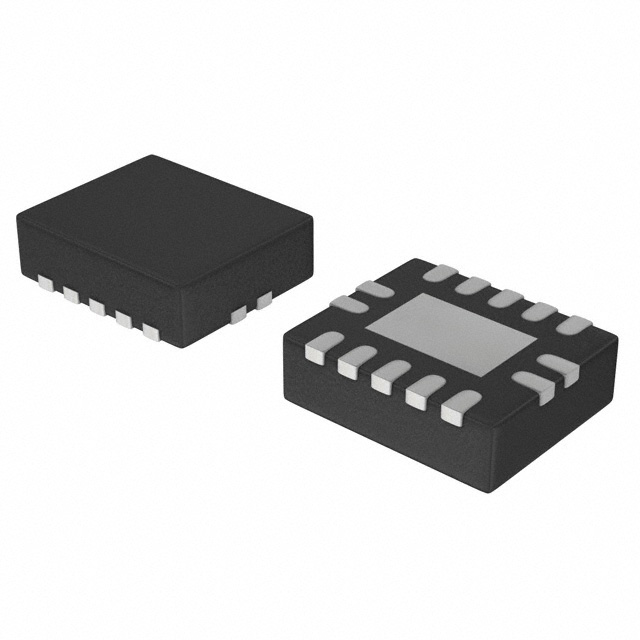
3. The input and output negative voltage ratings may be exceeded if the input and output clamp current ratings are observed. DescriptionThe 74LVT646 is a high-performance BiCMOS product designed for VCC operation at 3.3V.
This device consists of bus transceiver circuits with 3-State outputs, D-type flip-flops, and control circuitry arranged for multiplexed transmission of data directly from the input bus or the internal registers.
Data on the A or B bus will be clocked into the registers as the appropriate clock pin goes High.
Output Enable (
OE) and DIR pins of the 74LVT646 are provided to control the transceiver function. In the transceiver mode, data present at the high impedance port may be stored in either the A or B register or both.
The Select (SAB, SBA) pins determine whether data is stored or transferred through the device in realtime. The DIR determines which bus will receive data when the OE is active (Low).
In the isolation mode (
OE = High), data from Bus A may be stored in the B register and/or data from Bus B may be stored in the A register.
When an output function of the 74LVT646 is disabled, the input function is still enabled and may be used to store and transmit data. Only one of the two buses, A or B may be driven at a time. The examples on the next page demonstrate the four fundamental bus management functions that can be performed with the 74LVT646.

 74LVT646 Data Sheet