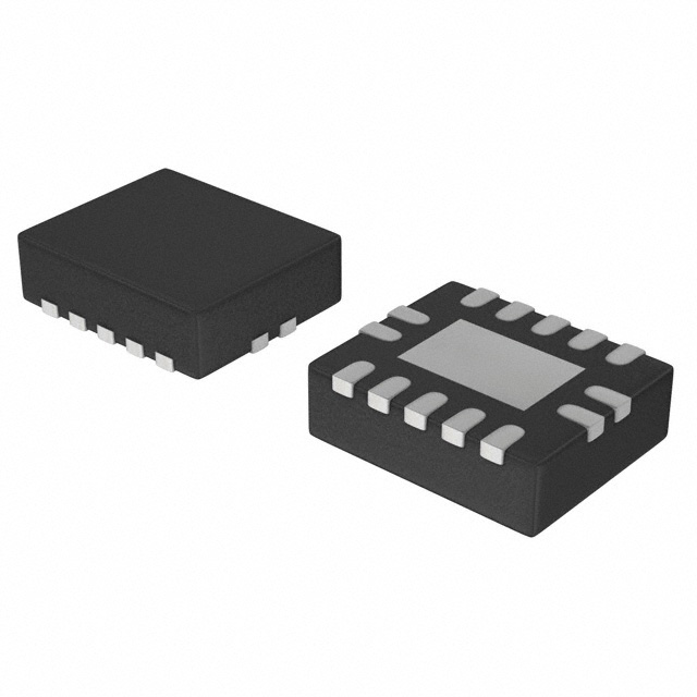
Features: Wide supply voltage range from 1.65 V to 5.5 V 5 V tolerant inputs for interfacing with 5 V logic High noise immunity Complies with JEDEC standard: JESD8-7 (1.65 V to 1.95 V) JESD8-5 (2.3 V to 2.7 V) JESD8B/JESD36 (2.7 V to 3.6 V). ±24 mA output drive (VCC = 3.0 V) ESD protection: HBM...
74LVC1G175: Features: Wide supply voltage range from 1.65 V to 5.5 V 5 V tolerant inputs for interfacing with 5 V logic High noise immunity Complies with JEDEC standard: JESD8-7 (1.65 V to 1.95 V) JESD8-5 (2.3...
SeekIC Buyer Protection PLUS - newly updated for 2013!
268 Transactions
All payment methods are secure and covered by SeekIC Buyer Protection PLUS.
Symbol | Parameter | Conditions | Min | Max | Unit |
VCC | supply voltage | -0.5 | +6.5 | V | |
IIK | input diode current | VI < 0 V | - | -50 | mA |
VI | input voltage | [1] -0.5 | +6.5 | V | |
VO | output voltage | active mode | [1] [2] -0.5 | VCC + 0.5 | V |
Power-down mode |
[1] [2] -0.5 |
+6.5 |
V | ||
IOK | output diode current | VO > VCC or VO < 0 V | - | ±50 | mA |
IO | output source or sink current |
VO = 0 V to VCC | - | ±50 | mA |
ICC, IGND | VCC or GND current | - | ±100 | mA | |
Tstg | storage temperature | -65 | +150 | °C | |
Ptot | power dissipation | Tamb = -40 °C to +125 °C | - | 250 | mW |
[1] The input and output voltage ratings may be exceeded if the input and output current ratings are observed.
[2] When VCC = 0 V (Power-down mode), the output voltage can be 5.5 V in normal operation.
The 74LVC1G175 is a high-performance, low-voltage, Si-gate CMOS device, superior to most advanced CMOS compatible TTL families.
The input can be driven from either 3.3 V or 5 V devices. This feature allows the use of this device in a mixed 3.3 V and 5 V environment.
The 74LVC1G175 is fully specified for partial power-down applications using Ioff. The Ioff circuitry disables the output, preve
nting the damaging backflow current through the device when it is powered down.
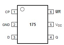
The 74LVC1G175 is a single positive edge triggered D-type flip-flop with individual data (D) input, clock (CP) input,master reset (MR) input, and Q output.
The master reset (MR) is an asynchronous active LOW input and operate independently of the clock input.Information on the data input is transferred to the Q output on the LOW-to-HIGH transition of the clock pulse. The D input must be stable one set-up time prior to the LOW-to-HIGH clock transition, for predictable operation.
Schmitt-trigger action of the 74LVC1G175 at all inputs makes the circuit highly tolerant to slower input rise and fall times.