74LVC161

Features: • Wide supply voltage range of 1.2 V to 3.6 V• In accordance with JEDEC standard no. 81A• Inputs accept voltages up to 5.5 V• CMOS low power consumption• Direct interface with TTL levels• Asynchronous reset• Synchronous counting and loading•...

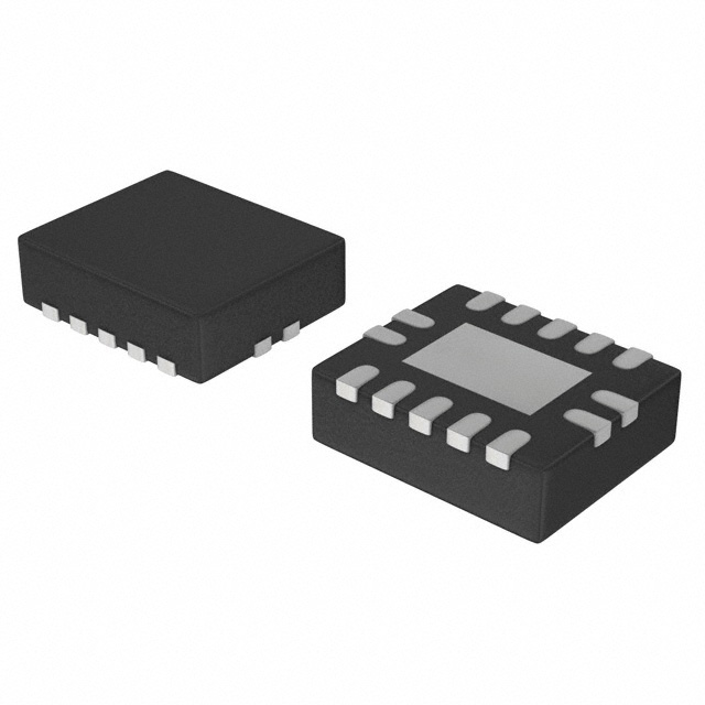
product image

74LVC161 Picture
SeekIC No. : 004251218 Detail

74LVC161: Features: • Wide supply voltage range of 1.2 V to 3.6 V• In accordance with JEDEC standard no. 81A• Inputs accept voltages up to 5.5 V• CMOS low power consumption• Dire...

floor Price/Ceiling Price

Part Number:
74LVC161
Supply Ability:
5000

Price Break

  • Qty
  • 1~5000
  • Unit Price
  • Negotiable
  • Processing time
  • 15 Days
Total Cost: $ 0.00

SeekIC Buyer Protection PLUS - newly updated for 2013!

  • Escrow Protection.
  • Guaranteed refunds.
  • Secure payments.
  • Learn more >>

Month Sales

268 Transactions

Rating

evaluate  (4.8 stars)

Upload time: 2024/12/21

Payment Methods

All payment methods are secure and covered by SeekIC Buyer Protection PLUS.

Notice: When you place an order, your payment is made to SeekIC and not to your seller. SeekIC only pays the seller after confirming you have received your order. We will also never share your payment details with your seller.
Product Details

Description


Features:

• Wide supply voltage range of 1.2 V to 3.6 V
• In accordance with JEDEC standard no. 81A
• Inputs accept voltages up to 5.5 V
• CMOS low power consumption
• Direct interface with TTL levels
• Asynchronous reset
• Synchronous counting and loading
• Two count enable inputs for nbit cascading
• Positive edgetriggered clock
• Output drive capability 50 transmission lines @85


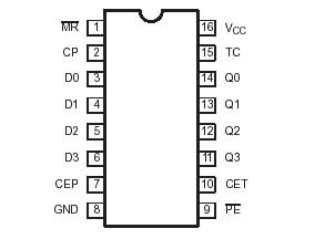
Pinout

  Connection Diagram


Specifications

In accordance with the Absolute Maximum Rating System (IEC 134)
Voltages are referenced to GND (ground = 0V)
SYMBOL PARAMETER CONDITIONS RATING UNIT
VCC DC supply voltage 0.5 to +6.5 V
IIK DC input diode current VI< 0 50 mA
VI DC input voltage Note 2 0.5 to +5.5 V
IOK DC output diode current VO >VCC or VO < 0 ±50 mA
VO DC output voltage Note 2 0.5 to Vcc +0.5 V
IO DC output source or sink current VO = 0 to Vcc ±50 mA
IGND, ICC DC VCC or GND current ±100 mA
Tstg Storage temperature range 60 to +150 °C
PTOT Power dissipation per package
plastic mini-pack (SO)
plastic shrink mini-pack (SSOP and TSSOP)
above +70°C derate linearly with 8 mW/K
above +60°C derate linearly with 5.5 mW/K
500
500
mW

NOTES:
1. Stresses beyond those listed may cause permanent damage to the device. These are stress ratings only and functional operation of the device at these or any other conditions beyond those indicated under "recommended operating conditions" is not implied. Exposure to absolute-maximum-rated conditions for extended periods may affect device reliability.

2. The input and output voltage ratings may be exceeded if the input and output current ratings are observed.


Description

The 74LVC161 is designed as a highperformance, lowpower, lowvoltage, sigate CMOS device and superior to most advanced CMOS compatible TTL families. It is a synchronous presettable binary counter which features an internal lookhead carry and can be used for highspeed counting. Synchronous operation is provided by having all flipflops clocked simultaneously on the positivegoing edge of the clock (CP).

It has many features. The first one is wide supply voltage range of the 74LVC161 1.2V to 3.6V. The second one is in accordance with JEDEC standard no. 81A. The third one is inputs accept voltages up to 5.5V. The fourth one is CMOS low power consumption. The fifth one is direct interface with TTL levels. The sixth one is asynchronous reset. The seventh one is synchronous counting and loading. The eighth one is two count enable inputs for nbit cascading. The ninth one is positive edgetriggered clock. The tenth one is output drive capability 50 transmission lines at 85°C.

Some absolute maximum ratings of the 74LVC161 have been concluded into several points as follow. The first one is about its DC supply voltage which would be from 0.5 to +6.50V. The second one is about its DC input diode current which would be -50mA. The third one is about its DC input voltage which would be from 0.5 to +5.5V. The fourth one is about its DC output diode current which would be +/-50mA. The fifth one is about its DC output voltage which would be from 0.5 to Vcc+0.5V. The sixth one is about its DC output source or sink current which would be +/-50mA. The seventh one is about its DC Vcc or GND current which would be +/-100mA. The eighth one is about its storage temperature range which would be from 65 to +150°C. The ninth one is about its power dissipation which would be 500mW. It should be noted that stresses beyond those listed may cause permanent damage to the device. Exposure to absolute maximum rated conditions for extended periods may affect device reliability. And so on. For more information of the 74LVC161 please contact us for details.

The 74LVC161 is a highperformance, lowpower, lowvoltage, Sigate CMOS device and superior to most advanced CMOS compatible TTL families.

The 74LVC161 is a synchronous presettable binary counter which features an internal lookhead carry and can be used for highspeed counting. nchronous operation is provided by having all flipflops clocked simultaneously on the positivegoing edge of the clock (CP). The outputs (Q0 to Q3) of the counters of the 74LVC161 may be preset to a HIGH or LOW level. A LOW level at the parallel enable input (PE) disables the counting action and causes the data at the data inputs (D0 to D3) to be loaded into the counter on the positivegoing edge of the clock (provided that the setup and hold time requirements for PE are met). Preset takes place regardless of the levels at count enable inputs (CEP and CET). A low level at the master reset input (MR) sets all four outputs of the flipflops (Q0 to Q3) to LOW level regardless of the levels at CP, PE, CET and CEP inputs (thus providing an asynchronous clear function).

The lookahead carry simplifies serial cascading of the counters. Both count enable inputs (CEP and CET) must be HIGH to count. The CET input is fed forward to enable the terminal count output (TC). The TC output thus enabled will produce a HIGH output pulse of a duration approximately equal to a HIGH level output of Q0. This pulse can be used to enable the next cascaded stage. The maximum clock frequency of the 74LVC161 for the cascaded counters is determined by the CP to TC propagation delay and CEP to CP setup time, according to the following formula:


Customers Who Bought This Item Also Bought

Margin,quality,low-cost products with low minimum orders. Secure your online payments with SeekIC Buyer Protection.
Power Supplies - External/Internal (Off-Board)
Power Supplies - Board Mount
Memory Cards, Modules
Boxes, Enclosures, Racks
LED Products
View more