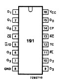
Features: · Synchronous reversible counting· Asynchronous parallel load· Count enable control for synchronous expansion· Single up/down control input· Output capability: standard· ICC category: MSIPinoutDescriptionThe 74HCT191 is high-speed Si-gate CMOS devices and are pin compatible with low powe...
74HCT191: Features: · Synchronous reversible counting· Asynchronous parallel load· Count enable control for synchronous expansion· Single up/down control input· Output capability: standard· ICC category: MSIP...
SeekIC Buyer Protection PLUS - newly updated for 2013!
268 Transactions
All payment methods are secure and covered by SeekIC Buyer Protection PLUS.
Features: · Output capability: standard· ICC category: SSIPinoutDescription The 74HC/HCT02 are hig...
Features: · Level shift capability· Output capability: standard (open drain)· ICC category: SSIPin...
The 74HCT191 is high-speed Si-gate CMOS devices and are pin compatible with low power Schottky TTL (LSTTL). They are specified in compliance with JEDEC standard no. 7A.
The 74HCT191 is asynchronously presettable 4-bit binary up/down counters. They contain four master/slave flip-flops with internal gating and steering logic to provide asynchronous preset and synchronous count-up and count-down operation.
Asynchronous parallel load capability permits the counter to be preset to any desired number. Information present on the parallel data inputs (D0 to D3) is loaded into the counter and appears on the outputs when the parallel load (PL) input is LOW. As indicated in the function table, this operation overrides the counting function.
Counting of the 74HCT191 is inhibited by a HIGH level on the count enable (CE) input. When CE is LOW internal state changes are initiated synchronously by the LOW-to-HIGH transition of the clock input. The up/down (U/D) input signal determines the direction of counting as indicated in the function table. The CE input may go LOW when the clock is in either state, however, the LOW-to-HIGH CE transition of the 74HCT191 must occur only when the clock is HIGH. Also, the U/D input should be changed only when either CE or CP is HIGH.