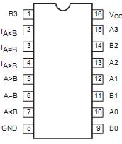
Features: *High-impedance NPN base inputs for reduced loading (20A in High and Low states)*Magnitude comparison of any binary words*Serial or parallel expansion without extra gatingApplication The parallel expansion scheme shown in Figure 1 demonstrates the most efficient general use of these com...
74F85: Features: *High-impedance NPN base inputs for reduced loading (20A in High and Low states)*Magnitude comparison of any binary words*Serial or parallel expansion without extra gatingApplication The ...
SeekIC Buyer Protection PLUS - newly updated for 2013!
268 Transactions
All payment methods are secure and covered by SeekIC Buyer Protection PLUS.
The parallel expansion scheme shown in Figure 1 demonstrates the most efficient general use of these comparators. The expansion inputs can be used as a fifth input bit position except on the least significant device, which must be connected as in the serial scheme.The expansion inputs used by labeling IA>B as an "A" input, as IA<B as a "B"input and setting IA=B= Low. The 74F85 can be used as a 5-bit comparator only when the outputs are used to drive the (A0-A3) an (B0-B3) inputs of another 74F85 device. The parallel technique can be expanded to any number of bits as shown in Table 1.
SYMBOL | PARAMETER | RATING | UNIT |
VCC | Supply voltage | 0.5 to +7.0 | V |
VIN | Input voltage | 0.5 to +7.0 | V |
IIN | Input current | 30 to +5 | mA |
VOUT | Voltage applied to output in High output state | 0.5 to +VCC | V |
IOUT | Current applied to output in Low output state | 40 | mA |
Tamb | Operating free-air temperature range | 0 to +70 | °C |
Tstg | Storage temperature | 65 to +150 | °C |
The 74F85 is a 4-bit magnitude comparator that can be expanded to almost any length. It compares two 4-bit binary, BCD, or other monotonic codes and presents the three possible magnitude results at the outputs. The 4-bit inputs are weighted (A0-A3) and (B0-B3) where A3 and B3 are the most significant bits. The operation of the 74F85 is described in the Function Table, showing all possible logic conditions. The upper part of the table describes the normal operation under all conditions that will occur in a single device or in a series expansion scheme. In the upper part of the table the three outputs are mutually exclusive. In the lower part of the table, the outputs reflect the feed-forward conditions that exist in the parallel expansion scheme. The expansion inputs IA>B, and IA=B and IA<B are the least significant bit positions. When used for series expansion, the A>B, A=B and A<B outputs of the lease significant word are connected to the corresponding IA>B, and IA=B and IA<B inputs of the next higher stage. Stages can be added in this manner to any length, but a propagation delay penalty of about 15ns is added with each additional stage. For proper operation of the 74F85, the expansion inputs of the least significant word should be tied as follows:IA>BLow,IA=B= High, and IA<B= Low.