74F807

Features: *High speed parallel registers with positive edge-triggered D-type flip-flops*High speed full adder*8-bit parity generator*High impedance PNP inputs for light bus loading*Center VCCand GND pins and controlled output buffers minimize*3-Stateglitch-free power-up uppower-down*Broadside pino...

product image

74F807 Picture
SeekIC No. : 004249858 Detail

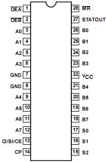
74F807: Features: *High speed parallel registers with positive edge-triggered D-type flip-flops*High speed full adder*8-bit parity generator*High impedance PNP inputs for light bus loading*Center VCCand GND...

floor Price/Ceiling Price

Part Number:
74F807
Supply Ability:
5000

Price Break

  • Qty
  • 1~5000
  • Unit Price
  • Negotiable
  • Processing time
  • 15 Days
Total Cost: $ 0.00

SeekIC Buyer Protection PLUS - newly updated for 2013!

  • Escrow Protection.
  • Guaranteed refunds.
  • Secure payments.
  • Learn more >>

Month Sales

268 Transactions

Rating

evaluate  (4.8 stars)

Upload time: 2024/5/31

Payment Methods

All payment methods are secure and covered by SeekIC Buyer Protection PLUS.

Notice: When you place an order, your payment is made to SeekIC and not to your seller. SeekIC only pays the seller after confirming you have received your order. We will also never share your payment details with your seller.
Product Details

Description


Features:

*High speed parallel registers with
  positive edge-triggered D-type flip-flops
*High speed full adder
*8-bit parity generator
*High impedance PNP inputs for light bus loading
*Center VCC and GND pins and controlled output buffers minimize
*3-State  glitch-free  power-up up  power-down
*Broadside pinout


Pinout

  Connection Diagram


Specifications

SYMBOL PARAMETER RATING UNIT
VCC Supply voltage 0.5 to +7.0 V
VIN Input voltage 0.5 to +7.0 V
IIN Input current 30 to +5 mA
VOUT Voltage applied to output in High output state 0.5 to +VCC V
IOUT Current applied to output in Low output state 48 mA
Tamb Operating free-air temperature range 0 to +70 °C
Tstg Storage temperature 65 to +150 °C


Description

    The 74F807 is a registered transceiver that also has the capability to perform count, shift, and add functions. It is also has the capability to generate a parity bit output. All of this is done within a 28-pin package.

    The MR input of the 74F807 is an overriding asynchronous reset which forces the STATOUT output low as well as the A and B busses.

    The A and B busses of the 74F807 have separate OE inputs (OEA, OEB]. These inputs have no bearing on the internal functioning of this device only on the output states. Both OE pins are enabled low.

    All operating modes of the 74F807, other than clear,3-State, and the two hold modes require the rising edge of the clock. All setup and hold times must be observed for proper functioning.

    Data of the 74F807 on the internal register can be switched on either the A or B ports for output.

   Depeding on the state of the select in-puts (S0, S1, S2), and carry in/ serial in/clock enable (CI/SI/CE), the 74F807 has nine distinct operating modes:

1. Add mode w/carry in-the CI/SI/Cinput is used as a carry in signal and the STATOUT output is the carry out signal.(In add mode the COUT is NOT registered. This means the carry output signal appears at the STATOUT output one clock prior to the related data.).  In this mode, the CI/SI/CE input is added to the register contents and to the inputs. (The adder uses only the An inputs, not the Bn inputs.)

2. Add mode wo/carry in-same as above except the CI/SI/CE input is not included in the addition.

3. Count w/count enable (count) - the CI/S CE input is now used as the count enable.input and the STATOUT output is terminal count. In this mode the CI/SI/CE input must be high to enable the count function. The register contents are incremented by one.

4. Count w/count enable (hold)- same  above except no incrementing occurs.

5. Count wo/count enable - same as number 3 except the CI/SI/CE  input has no control over counting or holding.

6. Shift -The CI/SI/CE  input now becomthe serial input and the STATOUT output becomes the serial output. In this mode the CI/SI/CE input is shifted into the Q0 register, Q0 into the Q1 register etc. The Q7 register is shifted into the STATOUT.

7. Load A inputs -The CI/SI/CE  input has no bearing in either of the load modes. The STATOUT output becomes the parity out.The parity out is high for an odd number of registered bits high, and low for even number of registered bits high (even parity). In this mode the An inputs are loaded into the internal register and output to the B bus. If OEA = low the internal register would wrap around and be loaded again.

8. Load B inputs - same as number except the A and B busses are switched.

9. Hold - Again the CI/SI/CE input is not used; the STATOUT output is still the parity out. In this mode either the A bus, B bus or both can be held with the registered data. No other operation is performed.


Customers Who Bought This Item Also Bought

Margin,quality,low-cost products with low minimum orders. Secure your online payments with SeekIC Buyer Protection.
Test Equipment
Memory Cards, Modules
Inductors, Coils, Chokes
Cables, Wires - Management
Sensors, Transducers
View more