
Circuit Diagram
Index 35
Santana 2000 gsi cars before the wind window wiper, before the wind window cleaners circuit diagram
Published:2014/1/16 18:36:00 Author: | Keyword: Santana 2000 gsi cars before the wind window wiper, before the wind window cleaners circuit diagram,
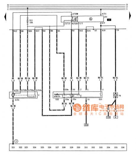
Figure santana 2000 gsi cars before the wind window wiper, before the wind window cleaners circuit diagram
E21 - the wind window cleaning pump switch E22 - before the wind window wiper switch J31 - wiper relay S11 - before the wind window wiper, cleaner fuse (15 a) V - the wind window wiper motor V4 - before the wind window cleaning pump (5) - pick up location (in the circuit board on the right side of the star grounding claw) (View)
View full Circuit Diagram | Comments | Reading(689)
Audio amplifier circuit diagram
Published:2014/1/16 18:35:00 Author: | Keyword: Audio amplifier circuit diagram,
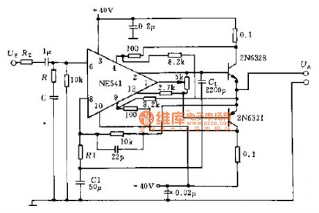
Diagram using NE541 high voltage power amplifier, current gain in 20 ~ HZ20KHZ frequency range is 90 db, at 300 mv RMS input, output high level RMS 20 v. integrated circuit internal equipped with short circuit protection. The external current limiting network to provide additional protection, two output transistor to increase the output power to 75 w, to drive the speakers.
Audio amplifier circuit diagram as shown
(View)
View full Circuit Diagram | Comments | Reading(1152)
Vibrating burglar alarm circuit
Published:2014/1/16 21:14:00 Author:lynne | Keyword: Vibrating burglar alarm circuit,
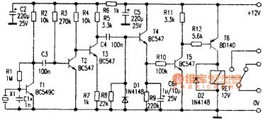
The alarms on the doors and windows using a hidden cheap piezo buzzer X1 as a sensor. This piezoelectric buzzer with bidirectional effect: when a voltage at both ends thereof, the piezoelectric ceramic material which will vibrate and produce a sound mechanical deformation; mechanical hand, when it is subjected to vibrations generated thief sound housebreaking When, at its ends will produce a corresponding output voltage.
>After the use of a property here, making it play a role in vibration sensor. As shown, the voltage generated by the piezoelectric sensor X1 transistor T1 of the first stage amplifier composed of the discharge is about 100 times. Effect transistor T2 from the detector, its collector voltage is only 50mv. Since R3 directly to the base of T2 being connected to the power line, T2 is always in the ON state can not afford to amplification. If you need to increase the magnification, you can change the upper end of R3 T2 collector received. The transistor T3 provides a voltage gain of about 3 times, and the drive pulse detector D1. When the input pulse level is high enough, T4 rapid charging to C6. After the pulse, C6 slow discharge through a high impedance circuit R9 and R10 and T5 base-emitter composed this discharge time determines the turn-on time of the relay. Therefore C6 capacity required by the test needs to decide its value can select between 1uF-10uF. Piezoelectric sensors X1 should use shielded cable to the input of the circuit Swiss, but the cable should be as short as possible. If radio frequency interference, as shown in dotted lines can be shown between the T1 connected to the base and to add a bypass RFI lnF ceramic capacitors. In use, a known vibration source (such as under normal environmental sounds produced) should be kept away from the sensor in order to avoid false triggering. When the relay is not working, the circuit consumes only a few milliamps. Vibrating burglar alarm circuit shown in Figure:
(View)
View full Circuit Diagram | Comments | Reading(1005)
Dongfeng Peugeot Citroen Picasso 2.0L car central door locking circuit
Published:2014/1/16 20:44:00 Author:lynne | Keyword: Dongfeng Peugeot Citroen Picasso 2.0L car central door locking circuit,
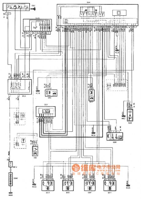
Dongfeng Peugeot Citroen Picasso 2.0L car central door locking circuit shown in Figure:
(View)
View full Circuit Diagram | Comments | Reading(806)
Dongfeng Peugeot Citroen Picasso 1.6L car central door locking circuit
Published:2014/1/16 20:43:00 Author:lynne | Keyword: Dongfeng Peugeot Citroen Picasso 1.6L car central door locking circuit,

Dongfeng Peugeot Citroen Picasso 1.6L car central door locking circuit shown in Figure:
(View)
View full Circuit Diagram | Comments | Reading(1164)
Siena passenger compartment lamp circuit
Published:2014/1/16 20:37:00 Author:lynne | Keyword: Siena passenger compartment lamp circuit,
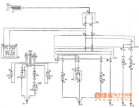
Siena passenger compartment lamp circuit shown in Figure:
(View)
View full Circuit Diagram | Comments | Reading(1784)
Siena turn signals lights and emergency lights circuit
Published:2014/1/16 20:36:00 Author:lynne | Keyword: Siena turn signals lights and emergency lights circuit,
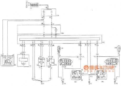
Siena turn signals lights and emergency lights circuit shown in Figure:
(View)
View full Circuit Diagram | Comments | Reading(1699)
Siena Wiper blade and the rear windshield heating circuit diagram
Published:2014/1/15 20:15:00 Author:lynne | Keyword: Siena Wiper blade and the rear windshield heating circuit diagram,

Siena Wiper blade and the rear windshield heating circuit diagram as shown:
(View)
View full Circuit Diagram | Comments | Reading(669)
The mouse electric schematic diagram
Published:2014/1/15 19:58:00 Author:lynne | Keyword: The mouse electric schematic diagram,
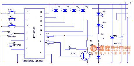
The mouse electric schematic diagram as shown:
(View)
View full Circuit Diagram | Comments | Reading(2530)
Changhong D2986-type color television circuit diagram
Published:2014/1/15 20:00:00 Author:lynne | Keyword: Changhong D2986-type color television circuit diagram,
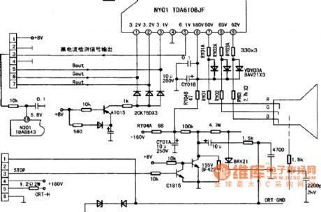
Changhong D2986-type color television circuit diagram shown in Fig.:
(View)
View full Circuit Diagram | Comments | Reading(1338)
Made of CD4069 voltage-controlled oscillator circuit diagram
Published:2014/1/15 20:08:00 Author:lynne | Keyword: Made of CD4069 voltage-controlled oscillator circuit diagram,
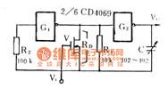
Made of CD4069 voltage-controlled oscillator circuit diagram as shown:
(View)
View full Circuit Diagram | Comments | Reading(1119)
Siena dashboard circuit diagram
Published:2014/1/15 20:09:00 Author:lynne | Keyword: Siena dashboard circuit diagram,

Siena dashboard circuit diagramshown in Figure:
(View)
View full Circuit Diagram | Comments | Reading(708)
Santana 2000 gsi type car electric circuit diagram window machine 1
Published:2014/1/15 18:33:00 Author: | Keyword: Santana 2000 gsi type car electric circuit diagram window machine 1,
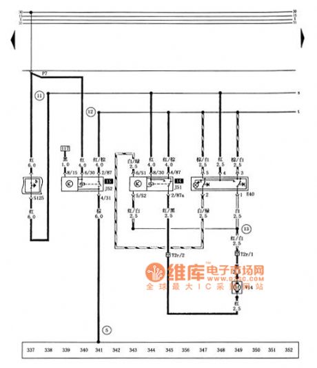
Tusangtana 2000GSi car electric window circuit diagram
E40-shaking windows switch J51-shaking windows down automatically relay J52-shaking windows delay relay S125-electric window executive protection T2r-electric window and electric window harness plug connector (2-pin, in Left front door) V14-left front window regulator motor ⑤ - ground (on the right side of the central star circuit board ground claw) - positive cable (in the electric window harness) - connection cable (in power shake harness the windows machine) - cable (in the electric window harness) (View)
View full Circuit Diagram | Comments | Reading(829)
Santana 2000 gsi type car electric circuit diagram window machine 2
Published:2014/1/15 18:32:00 Author: | Keyword: Santana 2000 gsi type car electric circuit diagram window machine 2,
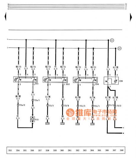
Tusangtana 2000GSi car electric window circuit diagram
E39-shaking windows safety switch (back door) E41-shaking windows switch (front left) E52-shaking windows switch (left rear) E54-shaking windows switch (right rear) T2s-electric window harness and electric window machine plug connector (2-pin, in the right front door) T3-electric window with the left rear window regulator harness plug connector (3-pin in the left rear door) T3i-electric window harness with the right rear window regulator plug connection (3-pin, in the right rear door) V15-right front window regulator motor - positive cable (in the electric window harness) - connection cable (in the electric window harness) (View)
View full Circuit Diagram | Comments | Reading(1053)
Overload and three sections of equalization circuit diagram
Published:2014/1/15 18:31:00 Author: | Keyword: Overload and three sections of equalization circuit diagram,
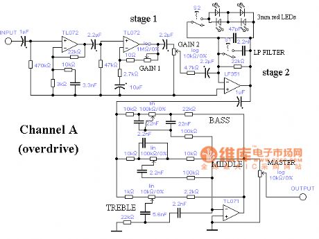
Overload and three sections of equalization circuit diagram as shown (View)
View full Circuit Diagram | Comments | Reading(953)
Santana 2000 gsi type car electric shake window machine, electric rearview mirror circuit diagram
Published:2014/1/15 18:30:00 Author: | Keyword: Santana 2000 gsi type car electric shake window machine, electric rearview mirror circuit diagram,

Tusangtana 2000GSi car electric window , electric mirrors schematics
E43- E48- electric mirror adjustment switch on switch electric mirrors converter E53- shaking on the left rear door window machine switch E55- right rear door window regulator switch S128- electric mirrors Fuse (3A) T2t- left rear windows shake switches and shaking windows machine motor plug connector ( 2-pin in the left rear door ) T2u- right rear power window switch and shaking windows machine motor plug connector ( 2-pin , in the right rear door ) T3j- left and left- front harness electric Mirrors plug connector ( 3-pin in the front left door ) T3k- right front door and right electric mirrors harness plug connector ( 3-pin , in the right front door ) T6a- electric mirrors harness and right front door harness plug connection ( 6-pin on the right side glove box ) T6b- electric mirrors harness and right front door harness plug connector ( 6 pin in the left center of the circuit board ) after the left rear window regulator V26- V27- motor motor Right shaking windows V33- left and down to adjust electric mirrors electric mirrors left motor V34- V35- right- left-right adjustment of the motor up and down to adjust electric mirrors electric motor V36- right- left mirror adjustment motor ⑤ - ground ( Right in the center of the circuit board side star ground claw ) ( 13 ) - cable ( in the left front door wiring harness ) (View)
View full Circuit Diagram | Comments | Reading(873)
LED flow display clocks hardware circuit diagram
Published:2014/1/15 18:29:00 Author: | Keyword: LED flow display clocks hardware circuit diagram,
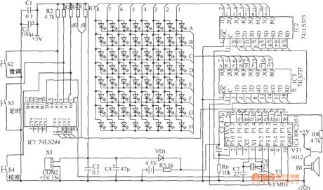
LED flow display clocks hardware circuit diagram
(View)
View full Circuit Diagram | Comments | Reading(1388)
PARCO color display video amplification circuit diagram
Published:2014/1/14 20:29:00 Author:lynne | Keyword: PARCO color display video amplification circuit diagram,
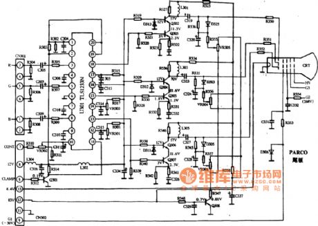
PARCO color display video amplification circuit diagram as shown:
(View)
View full Circuit Diagram | Comments | Reading(704)
Hisense HDP2908 type digital high-definition TV power main circuit diagram
Published:2014/1/14 20:21:00 Author:lynne | Keyword: Hisense HDP2908 type digital high-definition TV power main circuit diagram,

Hisense HDP2908 type digital high-definition TV power main circuit diagram as shown:
(View)
View full Circuit Diagram | Comments | Reading(1498)
TCL MF707 type sc-reens pincushion correction circuit diagram
Published:2014/1/14 20:20:00 Author:lynne | Keyword: TCL MF707 type sc-reens pincushion correction circuit diagram,
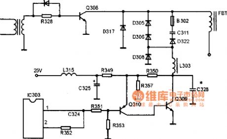
TCL MF707 type sc-reens pincushion correction circuit diagram as shown:
(View)
View full Circuit Diagram | Comments | Reading(1045)
| Pages:35/2234 At 202122232425262728293031323334353637383940Under 20 |
Circuit Categories
power supply circuit
Amplifier Circuit
Basic Circuit
LED and Light Circuit
Sensor Circuit
Signal Processing
Electrical Equipment Circuit
Control Circuit
Remote Control Circuit
A/D-D/A Converter Circuit
Audio Circuit
Measuring and Test Circuit
Communication Circuit
Computer-Related Circuit
555 Circuit
Automotive Circuit
Repairing Circuit