Circuit Diagram
Index 30
Fine wire used for lighting control circuit diagram
Published:2014/1/24 21:54:00 Author: | Keyword: Fine wire used for lighting control circuit diagram,
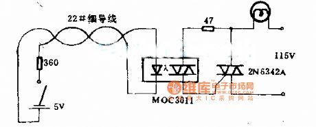
Fine wire used for lighting control circuit diagram
(View)
View full Circuit Diagram | Comments | Reading(826)
Santana 2000 gsi - gate AT starting motor and reversing light relay circuit diagram
Published:2014/1/24 21:47:00 Author: | Keyword: Santana 2000 gsi - gate AT starting motor and reversing light relay circuit diagram,
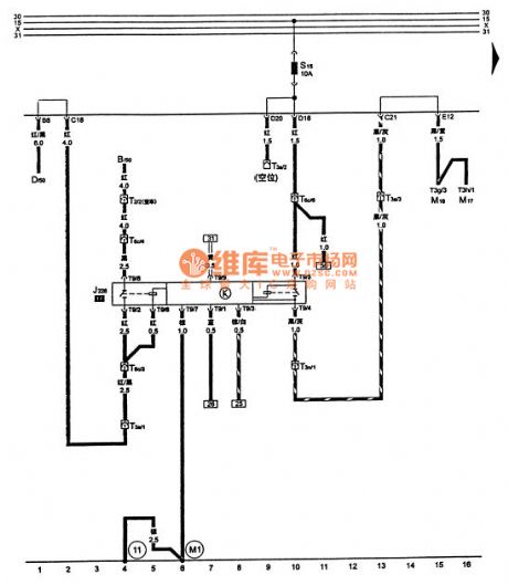

Tusangtana 2000GSi-AT starter motor lockout and reversing light relay circuit B-D-ignition starter switch J226-starter motor lockout and reversing light relay M16-M17-right-left reversing lights reversing lights S15-down lights, gear indicator shift lever lock solenoid fuse , 10A T2-engine wiring harness is connected to the generator harness connector, 2-pin, T3a-engine wiring harness and headlight harness plug is connected to the engine compartment in the middle frame, white, 3-pin, in the central electrical harness behind T3n-automatic transmission and the engine Right harness plug connection, white, 3-pin, in the central electrical harness behind T6c-automatic transmission and the engine wiring harness connector to connect the right, blue, 6-pin, behind the central electrical T9-automatic transmission harness and starter motor lockout and reversing light relay plug connector, 9-pin, in the central electrical - take place, in the right front seat underneath the car body - grounding cable in the automatic transmission wiring harness (View)
View full Circuit Diagram | Comments | Reading(1803)
Dongfeng Peugeot Citroen Picasso 2.0L car key not removed warning buzzer circuit diagram
Published:2014/1/24 20:35:00 Author:lynne | Keyword: Dongfeng Peugeot Citroen Picasso 2.0L car key not removed warning buzzer circuit diagram,

Dongfeng Peugeot Citroen Picasso 2.0L car keys are not removed warning buzzer circuit diagram shown in figure:
(View)
View full Circuit Diagram | Comments | Reading(1034)
Dongfeng Peugeot Citroen Picasso 2.0L car lights not closed warning buzzer circuit diagram
Published:2014/1/24 20:27:00 Author:lynne | Keyword: Dongfeng Peugeot Citroen Picasso 2.0L car lights not closed warning buzzer circuit diagram,

Dongfeng Peugeot Citroen Picasso 2.0L car lights not closed warning buzzer circuit diagram shown in figure:
(View)
View full Circuit Diagram | Comments | Reading(749)
American siren alarm circuit
Published:2014/1/24 20:22:00 Author:lynne | Keyword: American siren alarm circuit,
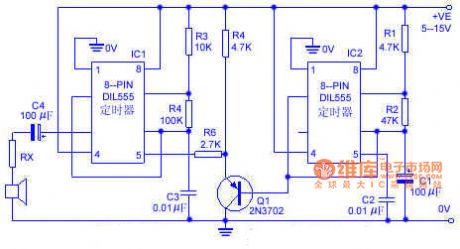
The circuit simulation an American siren sounds. IC2 is connected to a low-frequency multivibrator, the oscillation period is about 6s. C1 slowly changing ramp waveform applied to the PNP emitter follower Q1, and then applied to FM alarm generator IC1 through R6. IC1 natural center frequency of about 800Hz. Operation of the circuit is: alarm output signal from a low-frequency start, and then gradually rises to a high frequency within 3s, then dropped in the 3s to the original low frequency, and so forth continue. American siren alarm circuit shown in Figure:
(View)
View full Circuit Diagram | Comments | Reading(1412)
The active clamp resonant DC link inverter power circuit
Published:2014/1/24 20:17:00 Author:lynne | Keyword: The active clamp resonant DC link inverter power circuit,
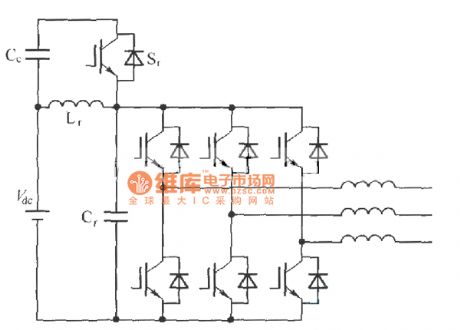
The active clamp resonant DC link inverter power circuit shown in Figure:
(View)
View full Circuit Diagram | Comments | Reading(894)
High loudness alert tone generator circuit diagram
Published:2014/1/24 20:10:00 Author:lynne | Keyword: High loudness alert tone generator circuit diagram, 1N4001, TWH8778

The warning tone generator circuit is simple, stable and reliable performance, working voltage 6V-12V, suitable for the siren in the car, motorcycle use. The circuit mainly by the sound IC KD ~ 9561 TWH8778 and switch integrated circuit composed of work by KD-9561 audio output warning signal after TWH8778 high current switching IC processing amplified loud speaker to promote sound the alarm. Components Selection: IC with KD-9561 sound IC, KD-9562 can also use sound IC, the wiring required to make sound an alarm tone alarm signal. IC2 use TWH8778 switching circuit, when the supply voltage is 12V, the speaker BL should choose 8Ω, 3W speakers or a dedicated number above drum speaker, current limiting resistor R1 resistance 300Ω ~ 510Ω, DW optional 3V regulator, VD is the circuit protection diodes can use 1N4001. High Loudness warning tone generator circuit shown in Figure:
(View)
View full Circuit Diagram | Comments | Reading(974)
Santana 2000 gsi - AT the control unit of automatic transmission, multi-function switch circuit diagram
Published:2014/1/24 20:21:00 Author: | Keyword: Santana 2000 gsi - AT the control unit of automatic transmission, multi-function switch circuit diagram,
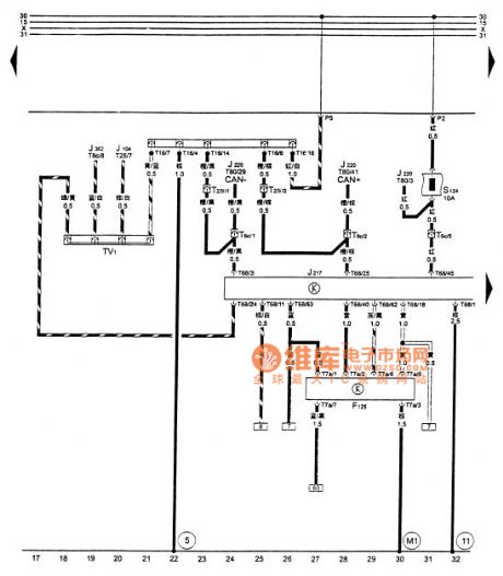
Tusangtana 2000GSi-AT automatic transmission control unit , multi-function switch circuit diagram
F125- multifunction switch in the rear of the transmission controller J217- J104-ABS automatic transmission control unit , in the right seat carpet J220-Motronic engine control unit , the air conditioner into the hood on the right side J362- alarm control unit , in the above S124- central electrical control unit of the engine , the automatic transmission control unit fuse , 10A T2 Ⅳ - automatic transmission harness is connected to the diagnostic connector harness , black, 2-pin , in the central rear T6c- automatic transmission of electrical harness and the right engine wiring harness, blue, 6-pin , T7a- automatic transmission wiring harness connector at the back of the center and the multi-function switch electrical plugs, black , 7-pin in the central electrical harness behind the dashboard T8c- alarm control unit with plug connection , black, 8-pin , the immobilizer control unit T16- fault diagnostic socket , black, 16-pin , in combination below T25-ABS and ABS controller harness connector plug meter , 25-pin , the ABS controller T68- automatic transmission and the transmission control unit harness connector , 68 pin on the transmission control unit T80- engine wiring harness , engine harness and engine control unit the right plug connector , 80-pin , the engine control unit TV1- line diagnostic socket attached to the 13th position on the central electrical ⑤ - take place in on the left side of the central star grounding prong electrical - ground cable harness in the automatic transmission - take place in the right front seat underneath the car body (View)
View full Circuit Diagram | Comments | Reading(1936)
Santana 2000 gsi - an automatic transmission control unit, solenoid valve, the transmission speed sensor, speed sensor circuit diagram
Published:2014/1/24 20:19:00 Author: | Keyword: Santana 2000 gsi - an automatic transmission control unit, solenoid valve, the transmission speed sensor, speed sensor circuit diagram,
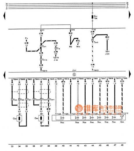
Tusangtana 2000GSi-AT automatic transmission control unit , solenoid valves, the transmission speed sensor, a vehicle speed sensor CircuitF- Brake Light Switch G38- transmission vehicle speed sensor , the transmission speed sensor on the left top of the G68- 1 , at the top right of the G93- transmission gearbox oil temperature sensor in the transmission of the flat -shaped wire controller J217- J104-ABS automatic transmission control unit , in the right seat carpet J220-Motronic engine control unit , the air conditioner into the hood to the right M9- M10- right- left brake light brake light N88- 1 N89- solenoid Valve solenoid Valve 2 N90- 3 N91- solenoid valve 4 N92- 5 N93- valve solenoid valve 6 N94- 7 S17- transmission control unit , engine control unit fuse , 10A T1a- headlights ABS harness connector and the harness connected to a pin, T2i- headlight harness and instrument panel harness electrical plug connector in the center back, white , 2-pin , in the central electrical behind T2 Ⅴ - automatic transmission harness and instrument panel harness plug connector , black, 2-pin , behind the central electrical T3l- automatic transmission and the transmission speed sensor wiring harness plug connectors attached harness , black, 3-pin , T3m- automatic transmission speed sensor harness and attach a harness plug connector at the rear of the automatic transmission , brown, 3-pin , automatic transmission rear T3n- automatic transmission harness Right connected to the engine wiring harness connector , white , 3-pin , in the central electrical harness behind T25-ABS and ABS controller plug connector , 25-pin , the ABS controller T68- automatic transmission and the transmission control unit harness plug connector , 68-pin , on the transmission control unit T80- engine wiring harness , engine harness and engine control unit the right plug connector , 80-pin , the engine control unit (View)
View full Circuit Diagram | Comments | Reading(2012)
Computer motherboard circuitry _01 6 oxt (1.0)
Published:2014/1/24 20:18:00 Author: | Keyword: Computer motherboard circuitry _01 6 oxt (1.0),

As shown in figure 6 oxt computer motherboard circuitry _01 (1.0) (View)
View full Circuit Diagram | Comments | Reading(756)
Computer motherboard circuitry _02 6 oxt (1.0)
Published:2014/1/24 20:16:00 Author: | Keyword: Computer motherboard circuitry _02 6 oxt (1.0),

As shown in figure 6 oxt computer motherboard circuitry _02 (1.0) (View)
View full Circuit Diagram | Comments | Reading(709)
Santana 2000 gsi - AT the control unit of automatic transmission, forced in low switch, shift lock check electromagnetic valve, gear lights circuit diagram
Published:2014/1/24 20:13:00 Author: | Keyword: Santana 2000 gsi - AT the control unit of automatic transmission, forced in low switch, shift lock check electromagnetic valve, gear lights circuit diagram,
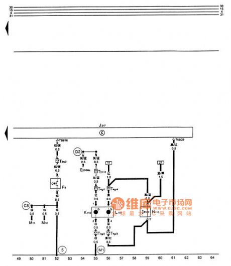


Figure santana 2000 gsi - AT the control unit of automatic transmission, forced in low switch, shift lock check electromagnetic valve, gear lights circuit diagram
E20 - the dashboard lighting regulator F8 - force in low switch, in the middle of the nacelle throttle zip L101 - shift lever on the lighting lamp and gear, the M11 in shift cover - the left turn signal M12 - the right turn signal J217 - automatic transmission control unit, in the right seat carpet K142 - shift lever below P/N warning lights, outpacing - shift in shift cover lock check electromagnetic valve, the shift lever on T2 Ⅴ - automatic transmission wire connected to the dashboard wiring harness plug, black, 2 needle, behind the central electric T3n - automatic transmission wire connected to the engine wiring harness plug right, white, 3 needles, behind the central electric T4g - automatic transmission wire connected to the gear indicator plug, 4 needle, below the shift lever T68 - automatic transmission wire connected to the transmission control unit plug, 68, on the transmission control unit (5) - ground, on the central electrical grounding on the left side of the star's paw - grounding cables, right at the engine wiring harness in D2 - cable (58) b - grounding cables within the dashboard harness, within the automatic transmission cable (View)
View full Circuit Diagram | Comments | Reading(1557)
Computer motherboard circuitry _03 6 oxt (1.0)
Published:2014/1/24 20:11:00 Author: | Keyword: Computer motherboard circuitry _03 6 oxt (1.0),

As shown in figure 6 oxt computer motherboard circuitry _03 (1.0) (View)
View full Circuit Diagram | Comments | Reading(688)
MOS image sensor oscilloscope married a circuit diagram
Published:2014/1/24 20:10:00 Author: | Keyword: MOS image sensor oscilloscope married a circuit diagram,
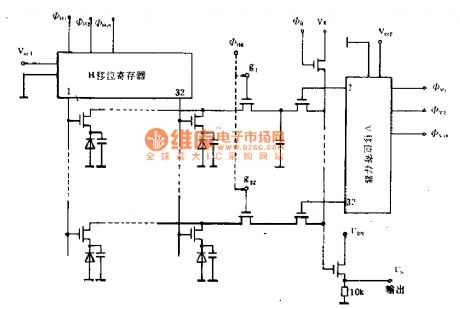

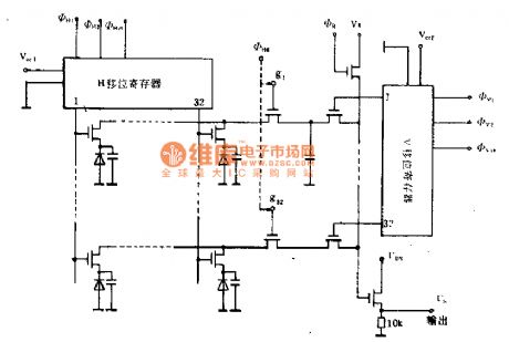
MOS image sensor oscilloscope married a circuit diagram
(View)
View full Circuit Diagram | Comments | Reading(926)
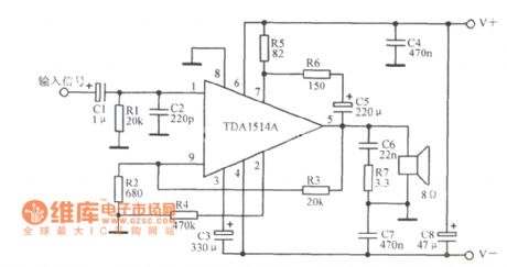
TDAl514A typical application circuit diagram
Published:2014/1/24 20:05:00 Author: | Keyword: TDAl514A typical application circuit diagram,
View full Circuit Diagram | Comments | Reading(1734)
Santana 2000 gsi - AT the ABS control unit, wheel speed sensor, electromagnetic valve circuit diagram
Published:2014/1/24 20:02:00 Author: | Keyword: Santana 2000 gsi - AT the ABS control unit, wheel speed sensor, electromagnetic valve circuit diagram,
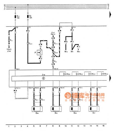
Tusangtana 2000GSi-AT ABS control unit , a wheel speed sensor, a circuit diagram of the solenoid valvesF- stop lamp switch after G44- G45- right wheel speed sensor front right , rear left wheel speed sensor G46- G47- left front wheel speed sensor wheel speed sensor controller J217- J104-ABS automatic transmission control unit , the carpet in the right seat Here J330- set locks shaking windows controller box at the top of the debris left brake lights M9- M10- M13- right brake lights brake lights N133-ABS Right backward oil solenoid valve N134-ABS Right out of the oil N135-ABS solenoid valve left backward N136-ABS oil out of the oil left rear brake light valve S2- fuse , 10A S12-ABS control , the automatic transmission control unit fuse , 15A T1a- headlights ABS harness connector and harness connection , a needle , in the central electrical harness behind T1e-ABS and electric window harness plug connector , a pin , T2i- headlight wiring harness connector at the back of the central instrument panel harness electrical connector , 2-pin , behind the central electrical T2l -ABS wiring harness connector and the right rear speed sensor connector , 2-pin , in the right rear seat following T2k-ABS harness and left rear speed sensor plug connection , two needles in the left rear seat below T2 Ⅴ - automatic transmission harness and instrument panel harness plug connector , black, 2-pin , in the central electrical harness behind T25-ABS and ABS controller plug connector , 25-pin , on the ABS controller T25a- remote / centralized control and centralized control harness connector lock lock / power window controller plugs, 25-pin , T68- automatic transmission and the transmission control unit harness connector is connected to the central control lock / power window controller , 68-pin , the transmission control unit (View)
View full Circuit Diagram | Comments | Reading(2187)
Computer motherboard circuitry _04 6 oxt (1.0)
Published:2014/1/24 20:01:00 Author: | Keyword: Computer motherboard circuitry _04 6 oxt (1.0),
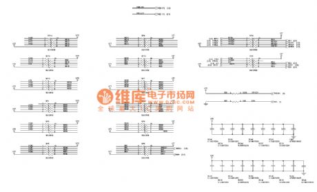
As shown in figure 6 oxt computer motherboard circuitry _04 (1.0) (View)
View full Circuit Diagram | Comments | Reading(699)
Santana 2000 gsi - AT the ABS control unit, ABS hydraulic pump and electromagnetic valve circuit diagram
Published:2014/1/23 23:22:00 Author: | Keyword: Santana 2000 gsi - AT the ABS control unit, ABS hydraulic pump and electromagnetic valve circuit diagram,
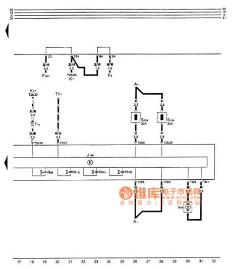
Figure santana 2000 gsi - AT the ABS control unit, ABS hydraulic pump and electromagnetic valve circuit diagram
A - battery F9 - hand brake lamp switch F34 - brake liquid level alarm switch J104 - ABS controller K7 instructions - hand brake and brake level warning light K47 - ABS warning light N99 - ABS right front feed N100 - ABS solenoid right front left anterior feed oil solenoid valve N101 - ABS solenoid valve N102 - ABS left before the oil T1k - dashboard harness with ABS solenoid wiring harness connector, 1 needle, behind the central electric T2j - ABS hydraulic pump and the control unit plug connection, 2 needle, T25 - ABS wiring harness on the ABS control unit and ABS controller plug connection, 25 needles, TV1 - diagnosis line socket on ABS controller, additional in central electric throne V64 13 - ABS hydraulic pump (View)
View full Circuit Diagram | Comments | Reading(1662)
MOS image sensor oscilloscope circuit diagram 2 a family
Published:2014/1/23 23:19:00 Author: | Keyword: MOS image sensor oscilloscope circuit diagram 2 a family,

MOS image sensor oscilloscope circuit diagram 2 a family
(View)
View full Circuit Diagram | Comments | Reading(782)
MOS image sensor oscilloscope circuit diagram 3 a family
Published:2014/1/23 23:17:00 Author: | Keyword: MOS image sensor oscilloscope circuit diagram 3 a family,
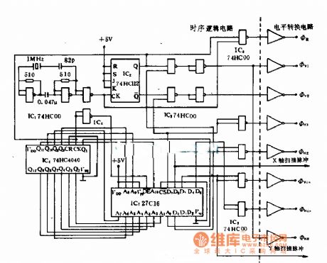
MOS image sensor oscilloscope circuit diagram 3 a family
(View)
View full Circuit Diagram | Comments | Reading(943)
| Pages:30/2234 At 202122232425262728293031323334353637383940Under 20 |
Circuit Categories
power supply circuit
Amplifier Circuit
Basic Circuit
LED and Light Circuit
Sensor Circuit
Signal Processing
Electrical Equipment Circuit
Control Circuit
Remote Control Circuit
A/D-D/A Converter Circuit
Audio Circuit
Measuring and Test Circuit
Communication Circuit
Computer-Related Circuit
555 Circuit
Automotive Circuit
Repairing Circuit
