Circuit Diagram
Index 2209
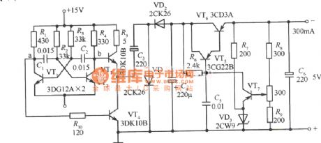
Automatic protection DC Power Supply circuit diagram preventing PC power-down
Published:2011/3/28 3:43:00 Author:Nicole | Keyword: DC Power Supply
View full Circuit Diagram | Comments | Reading(483)
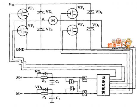
DC motor bridge drive circuit diagram
Published:2011/3/28 4:05:00 Author:Nicole | Keyword: DC motor, bridge drive
View full Circuit Diagram | Comments | Reading(587)
Low-cost and high power submultiple electronic rectifier circuit diagram
Published:2011/3/28 4:13:00 Author:Nicole | Keyword: electronic rectifier, submultiple
View full Circuit Diagram | Comments | Reading(608)
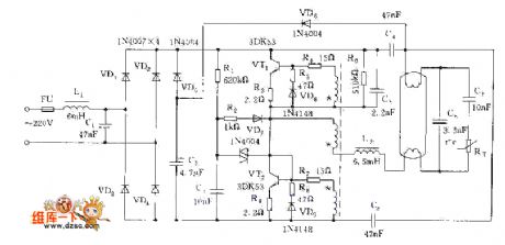
Practical electronic rectifier circuit diagram
Published:2011/3/28 4:13:00 Author:Nicole | Keyword: electronic rectifier
View full Circuit Diagram | Comments | Reading(572)
Sourcefree buzzer drive circuit diagram
Published:2011/3/20 22:55:00 Author:Ecco | Keyword: Sourcefree buzzer, drive

Sourcefree buzzer drive circuit diagram is as below:
(View)
View full Circuit Diagram | Comments | Reading(458)
Optically controlled circuitry diagram
Published:2011/3/20 22:55:00 Author:Ecco | Keyword: Optically controlled circuitry

Optically controlled circuitry diagram is as below:
(View)
View full Circuit Diagram | Comments | Reading(508)
Turning +15V power supply into -5V power supply fixed voltage power supply circuit diagram
Published:2011/3/22 4:27:00 Author:Rebekka | Keyword: fixed voltage power supply
View full Circuit Diagram | Comments | Reading(568)
±15V Tracking Regulator Power Supply Circuit Diagram 2
Published:2011/3/22 4:32:00 Author:Rebekka | Keyword: Tracking Regulator
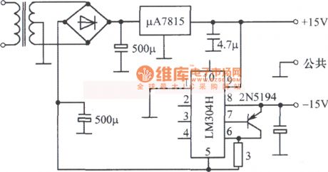
±15V Tracking Regulator Power Supply Circuit Diagram2 is shown as below.
(View)
View full Circuit Diagram | Comments | Reading(532)
ATS anti-thief system circuit diagram
Published:2011/3/20 22:53:00 Author:Ecco | Keyword: ATS anti-thief system
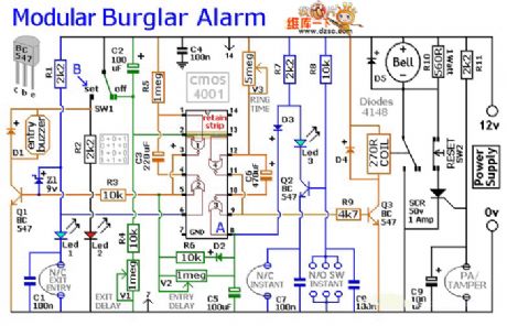
ATS anti-thief system circuit diagram is as below:
(View)
View full Circuit Diagram | Comments | Reading(3760)
Neon high pressure power supply circuit
Published:2011/3/25 0:32:00 Author:Joan | Keyword: Neon, power supply , high pressure
View full Circuit Diagram | Comments | Reading(968)
Constant current source circuit with adjustable output current
Published:2011/3/25 0:38:00 Author:Joan | Keyword: Constant current source , adjustable output current , three-terminal fixed output , integrated voltage regulator
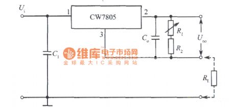
Above is Constant current source circuit with adjustable output current consisted of three-terminal fixed output integrated voltage regulator. (View)
View full Circuit Diagram | Comments | Reading(696)
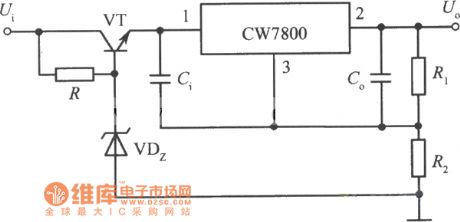
High input - high output integrated voltage regulator circuit 3
Published:2011/3/24 23:06:00 Author:Joan | Keyword: High input , high output , integrated voltage regulator
View full Circuit Diagram | Comments | Reading(562)
Telephone Schematic
Published:2011/3/21 1:28:00 Author:Joan | Keyword: Telephone

The figure is Telephone Schematic. (View)
View full Circuit Diagram | Comments | Reading(3918)
LED drive circuit diagram
Published:2011/3/20 22:51:00 Author:Ecco | Keyword: LED drive

LED drive circuit diagram is as below:
(View)
View full Circuit Diagram | Comments | Reading(503)
The inside circuit diagram of crystal triode MFJ6668
Published:2011/3/20 22:51:00 Author:Ecco | Keyword: crystal triode
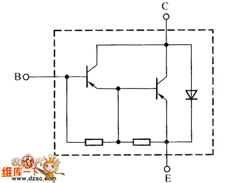
The inside circuit diagram of crystal triode MFJ6668 is as below:
(View)
View full Circuit Diagram | Comments | Reading(421)
Driving buzzer circuit diagram in power driving level
Published:2011/3/29 1:52:00 Author:Ecco | Keyword: Driving buzzer, power driving level

Driving buzzer circuit diagram in power driving level is as below:
(View)
View full Circuit Diagram | Comments | Reading(2622)
KangBao C12C - 15B induction cooker power driving output stage circuit diagram
Published:2011/3/29 1:57:00 Author:Ecco | Keyword: induction cooker , power driving output stage

KangBao C12C - 15B induction cooker power driving output stage circuit diagram is as below:
(View)
View full Circuit Diagram | Comments | Reading(2550)
LED display circuit diagram driving by 74HC595
Published:2011/3/28 22:11:00 Author:Ecco | Keyword: LED display

LED display circuit diagram driving by 74HC595 is as below:
(View)
View full Circuit Diagram | Comments | Reading(3932)
Control and display circuit diagram of Koltai T - 9328 amplifier
Published:2011/3/28 22:16:00 Author:Ecco | Keyword: Control circuit, display circuit , Koltai amplifier

Control and display circuit diagram of Koltai T - 9328 amplifier is as below:
(View)
View full Circuit Diagram | Comments | Reading(360)
LM317 adaptive adjustable regulated voltage supply circuit diagram
Published:2011/3/28 22:55:00 Author:Ecco | Keyword: regulated voltage supply

The power supply is LM317 regulated voltage components, which is use in adaptive circuitry. According to the output voltage , the circuitry will change the input voltage automatically to reduce the differential pressure between the input and output. And that can reduce the power cost of the power supply itself. Among them, VD5, VW, VT2 R5, R6, C10 and relay K constitute of adaptive switching action circuit, when output voltage Vo is lower than 14V, Vw will be stopped as lacking of breakdown voltage and no current pass it, VT2, K stop and K-1 is in closed state, the 14 V secondary voltage of transformer alternating current access regulated voltage circuitry. Or, when the output voltage is higher than 14V, VW is brokendown, VT2 is conducted. K gets electron, and K-1 moves to make 280V ac voltage access circuitry. Ensuring the differential pressure between the input and output does not exceed 15V. The output of the circuitry is continuously adjustable in 1.25 ~ 30V, and the maximum current is 3A.
(View)
View full Circuit Diagram | Comments | Reading(3627)
| Pages:2209/2234 At 2022012202220322042205220622072208220922102211221222132214221522162217221822192220Under 20 |
Circuit Categories
power supply circuit
Amplifier Circuit
Basic Circuit
LED and Light Circuit
Sensor Circuit
Signal Processing
Electrical Equipment Circuit
Control Circuit
Remote Control Circuit
A/D-D/A Converter Circuit
Audio Circuit
Measuring and Test Circuit
Communication Circuit
Computer-Related Circuit
555 Circuit
Automotive Circuit
Repairing Circuit

