
Circuit Diagram
Index 2196
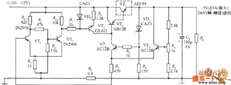
Three-phase bridge full-controlled rectifier and single-phase AC voltage driving circuit diagram
Published:2011/3/28 1:48:00 Author:Rebekka | Keyword: Full-controlled rectifier, Three-phase bridge, single-phase AC voltage driving
Three-phase bridge full-controlled rectifier and single-phase AC voltage driving circuit diagram is shown as below.
(View)
View full Circuit Diagram | Comments | Reading(1233)
Semiconductor laser driver circuit diagram
Published:2011/3/29 3:55:00 Author:Rebekka | Keyword: Semiconductor laser
Semiconductor laser driver circuit diagram is shown as below.
(View)
View full Circuit Diagram | Comments | Reading(1313)
Electronic absorb dome light circuit and maintenance circuit
Published:2011/3/30 21:22:00 Author:Jessie | Keyword: absorb dome light, maintenance
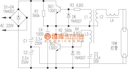
AC 220V rectified by the D1 ~ D4, C1, C2 filtering. C1 and C2 are series, can directly supply powertotubes to save charging capacitance, also reduced the compression requirements. R1 is startup resistance, provides BG2 forneeded initial voltage, R2 is bias resistors, BG1, BG2 and L1, L2, L3 compose theoscillating circuit, diodeD5 provides dischargecircuit for C3. L1 and L3 respectively connected to the bases of BG1 and BG2, which makes BG1 and BG2 get positive feedback voltageto initial. So that BG1 and BG2 turn in connected. High-frequency voltage formed in tubeto lighten it.
(View)
View full Circuit Diagram | Comments | Reading(698)
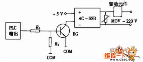
Touch switch circuit diagram
Published:2011/3/30 20:40:00 Author:Jessie | Keyword: Touch switch

In beginning, J inthe state of losing electricity. When using, handle the open, the human body induction signal amplified by BG1 ~BG3, J sucks close, meanwhile J - 1 sucks and make J self-locked. When need to shut off, handle the close, the human body induction signal amplified by BG4 ~BG5, bypass BG2 base current, J release, circuit is back again. When making circuit BG1 ~ BG5's BVceo > 30V, BG1, BG3, BG4, BG5's β>50, BG2's β>80, the unit of capacitance is µF/V. After installeditcan work without debugging. When this switch device shuts off the power, power consumption is close to zero, turn-on'spower < 0.5 W, switch devices using voltage range> 130V ~ 250V.
(View)
View full Circuit Diagram | Comments | Reading(582)
Working in -55℃~71℃ 6V fixed voltage power supply circuit diagram
Published:2011/3/22 22:55:00 Author:Rebekka | Keyword: Working in -55℃~71℃ 6V, fixed voltage power supply

Working in -55℃~71℃ 6V fixed voltage power supply circuit diagram is shown as below.
(View)
View full Circuit Diagram | Comments | Reading(646)
Automatic hand washing device circuit with SM9576
Published:2011/3/29 20:34:00 Author:Jessie | Keyword: hand washing device
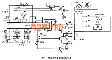
Automatic hand washing device circuit is shownin the figure 1. 220V AC power is step-down by transformer, V1 ~ V4 bridge rectifier, C1 is filteredto 9VDC power, this power supply to relay K1 ~ K3 as work power, then become 3V DC powersupplied toSM9576 as work power. The core device of automatic hand washing device circuit is SM9576, it contains infraredtransmit drive circuit and infrared receiving amplify circuit, its reception is decided by the size of the capacity of the sensitivity, when the C7 is in 0.01 ~ 0.1 u F, the receiving distance is changingbewteen 5 ~ 25cm.
(View)
View full Circuit Diagram | Comments | Reading(922)
With short-circuit protection fixed voltage power supply circuit diagram
Published:2011/3/22 22:53:00 Author:Rebekka | Keyword: With short-circuit protection, fixed voltage power supply
With short-circuit protection fixed voltage power supply circuit diagram is shown as below.
(View)
View full Circuit Diagram | Comments | Reading(763)
Power MOSFET high-speed driver circuit diagram
Published:2011/3/28 20:59:00 Author:Rebekka | Keyword: Power MOSFET, high-speed driver

Power MOSFET high-speed drive circuit diagram is shown as below.
(View)
View full Circuit Diagram | Comments | Reading(1655)
Solenoid valve AC contactor driver circuit diagram
Published:2011/3/28 21:01:00 Author:Rebekka | Keyword: Solenoid valve, AC contactor
Solenoid valve AC contactor driver circuit diagram is shown as below.
(View)
View full Circuit Diagram | Comments | Reading(1649)
74 series digital circuit of 74110 74F110 input J - K master-slave flip-flop
Published:2011/3/30 2:24:00 Author:Ecco | Keyword: digital circuit, input J - K , master-slave flip-flop
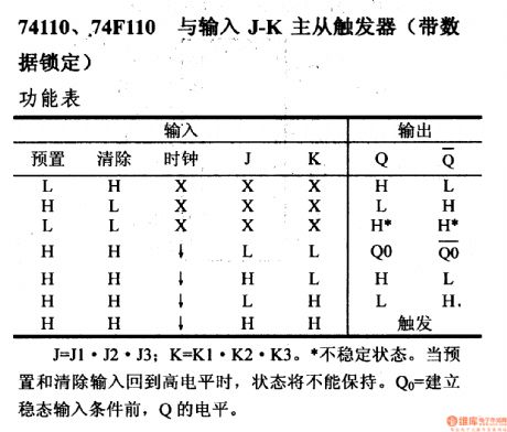
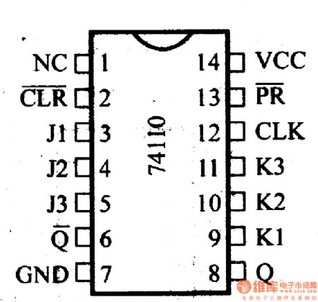
74110 74F110 input J - K master-slave flip-flop(with data caging function)
Unsteady state. When the preset and remove terminal return in high level, the state could not be kept. And the level of Qo is equal to Q before eatablishing steadystate input.
(View)
View full Circuit Diagram | Comments | Reading(459)
Push-pull structure piezoelectric stack driver circuit diagram
Published:2011/3/28 21:03:00 Author:Rebekka | Keyword: Push-pull structure, piezoelectric stack driver
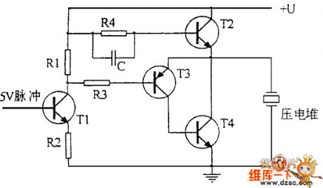
Push-pull structure piezoelectric stack driver circuit diagram is shown as below.
(View)
View full Circuit Diagram | Comments | Reading(1464)
74 series digital circuit of 74111 74F111 double J - K flip-flop
Published:2011/3/30 2:30:00 Author:Ecco | Keyword: digital circuit, double J - K flip-flop
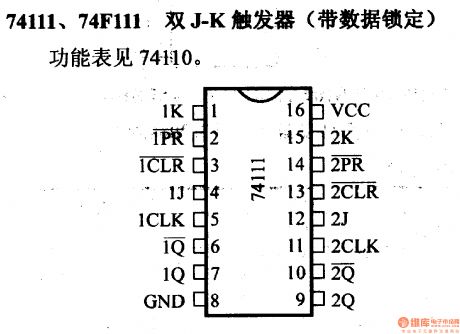
74 series digital circuit of 74111 74F111 double J - K flip-flop(with data caging function)
(View)
View full Circuit Diagram | Comments | Reading(1491)
Power transistor high and low voltage drive circuit diagram
Published:2011/3/28 21:10:00 Author:Rebekka | Keyword: High and low voltage drive, Power transistor
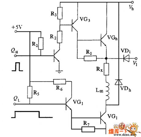
Power transistor high and low voltage drive circuit diagram is shown as below.
(View)
View full Circuit Diagram | Comments | Reading(598)
74 series digital circuit of 74LS114A 74F114 double J - K negative edge trigger
Published:2011/3/29 22:38:00 Author:Ecco | Keyword: digital circuit , double J - K negative edge , trigger
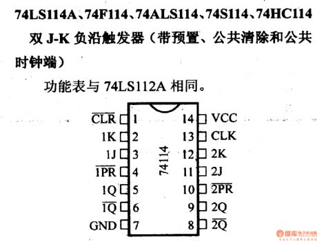
74LS114A,74F114, 74ALS114, 74S114, 74HC114double J - K negative edge trigger(with preset, public clear and clock terminal)
(View)
View full Circuit Diagram | Comments | Reading(480)
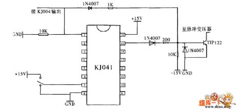
Plasma gun driver circuit diagram
Published:2011/3/28 21:11:00 Author:Rebekka | Keyword: Plasma gun, driver circuit

Plasma gun driver circuit diagram is shown as below.
(View)
View full Circuit Diagram | Comments | Reading(1110)
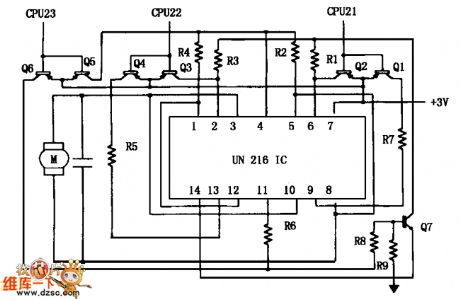
Zoom DC motor driver circuit diagram
Published:2011/3/28 21:14:00 Author:Rebekka | Keyword: Motor drive, Zoom DC
Zoom DC motor driver circuit diagram is shown as below.
(View)
View full Circuit Diagram | Comments | Reading(637)
74 series digital circuit of 74121 74L121 monostable multivibrator
Published:2011/3/30 2:39:00 Author:Ecco | Keyword: digital circuit, monostable multivibrator


To improve the precision and repeatability of the pulse width, it could connect a resistance between REXT/CEXT and VCC, and open for RINT.
To improve pulse width, it could connect atiming resistance betweenREXT/CEXT and CEXT. (View)
View full Circuit Diagram | Comments | Reading(1319)
74 series digital circuit of 74122 74L122 monostable multivibrator
Published:2011/3/30 2:43:00 Author:Ecco | Keyword: digital circuit, monostable multivibrator

To improve the precision and repeatability of the pulse width, it could connect a resistance between REXT/CEXT and VCC, and open for RINT. In order to get the variable pulse width, it could connect a variable resistance between RINT and VCC. (View)
View full Circuit Diagram | Comments | Reading(1311)
Chopper structure of single-tube driver circuit diagram
Published:2011/3/28 2:29:00 Author:Rebekka | Keyword: Chopper structure of single-tube, driver circuit

Chopper structure of single-tube driver circuit diagram is shown as below.
(View)
View full Circuit Diagram | Comments | Reading(624)
74 series digital circuit of 74123 74L123 double monostable multivibrator
Published:2011/3/30 1:42:00 Author:Ecco | Keyword: digital circuit, double monostable multivibrator


Capacitance. To improve the precision and repeatability of the pulse width, it could connect a resistance between REXT/CEXT and VCC, and open for RINT. In order to get the variable pulse width, it could connect a variable resistance between RINT and VCC.
74123, 74L123, 74LS123, 74HC123 double monostable multivibrator (View)
View full Circuit Diagram | Comments | Reading(753)
| Pages:2196/2234 At 2021812182218321842185218621872188218921902191219221932194219521962197219821992200Under 20 |
Circuit Categories
power supply circuit
Amplifier Circuit
Basic Circuit
LED and Light Circuit
Sensor Circuit
Signal Processing
Electrical Equipment Circuit
Control Circuit
Remote Control Circuit
A/D-D/A Converter Circuit
Audio Circuit
Measuring and Test Circuit
Communication Circuit
Computer-Related Circuit
555 Circuit
Automotive Circuit
Repairing Circuit