
Circuit Diagram
Index 1526
maverick 2005 roof open board circuit
Published:2011/7/15 1:58:00 Author:Fiona | Keyword: roof open board

View full Circuit Diagram | Comments | Reading(451)
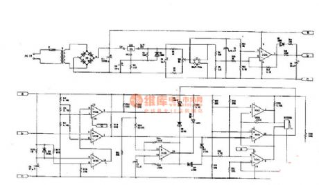
maverick 2005 body light circuit
Published:2011/7/15 1:59:00 Author:Fiona | Keyword: body light

View full Circuit Diagram | Comments | Reading(410)
Maverick 2005 electric windows circuit Figure 1
Published:2011/7/15 2:01:00 Author:Fiona | Keyword: electric windows

View full Circuit Diagram | Comments | Reading(419)
Maverick 2005 electric windows circuit
Published:2011/7/15 2:02:00 Author:Fiona | Keyword: electric windows

View full Circuit Diagram | Comments | Reading(412)
Sensor Circuit 101:CO gas sensor interface circuit
Published:2011/7/13 3:55:00 Author:zj | Keyword: Sensor Circuit 101, CO gas sensor, interface circuit
View full Circuit Diagram | Comments | Reading(1364)
Five control lamp switch circuit
Published:2011/7/5 21:29:00 Author:zj | Keyword: Five control, lamp switch circuit

As the Figure shows, it isa five control switch circuit. S1 ~ S5 are respectively arranged in 5 different places, but they can independently control lamp E lit or extinguished. Among them: S1, S5 1 x 2 single-pole double-throw switch, S2 ~ S4 with 2 x 2 double pole double throw switch. (View)
View full Circuit Diagram | Comments | Reading(587)
Radio remote control lamp switch circuit
Published:2011/7/5 21:25:00 Author:zj | Keyword: Radio remote control, lamp switch circuit

As shown in the figure itis a simple radio remote control lamp switch, press the launcher button lights ; click again, the light went out.Using themis very convenient. (View)
View full Circuit Diagram | Comments | Reading(887)
Radio remote control dimmer circuit
Published:2011/7/5 21:20:00 Author:zj | Keyword: Radio remote control, dimmer circuit

As shown in the diagram above, it is a radio remote control dimmer circuit. The radio remote control dimmer circuit adopts micro radio transmit/receive module and light modulation ASIC. So the circuit is concise and easy to produce. It works reliably. And the whole switch has only two wires for output.It can directly use it to replace the ordinary lighting switch, general lighting to remote dimmer light, without having to change the original indoor wiring. (View)
View full Circuit Diagram | Comments | Reading(2373)
Delay lamp circuit using relay (1)
Published:2011/7/7 22:01:00 Author:zj | Keyword: Delay lamp circuit, using relay

As the figue shows, it is a delay lamp using relay. It adopts the feature of relay control that the power of controlled lamp is only limited by relay contact. So you just need to use relay which has enough contact capacity. With this you can increase the power of controlled lamp. And the controlled device is not confined to the incandescent lamp. It is suitable for fluorescent lamps, electronic energy-saving lamps and other electrical devices. (View)
View full Circuit Diagram | Comments | Reading(757)
Delay lamp circuit using relay (7)
Published:2011/7/6 22:18:00 Author:zj | Keyword: Delay lamp circuit, using relay

As shown in the circuit, it uses a PTC thermistor as a control element, so that the circuit is very simple. SB1 and SB2 are lights button respectively installed in two different places. Both of them can operate E. K should adopt the JRX-13F type miniature electromagnetic relay ; PTC can use color TV degaussing resistor, such as MZ72-18 type. (View)
View full Circuit Diagram | Comments | Reading(1126)
The simple automatic charger
Published:2011/7/17 19:26:00 Author:TaoXi | Keyword: simple, automatic, charger


This circuit is simple, the components are easy to find, it charges the nickel cadmium batteries respectively, when the power is full, the circuit will stop automaticly. The circuit is as shown in the figure, before the charging, you need to adjust R4 to make the output voltage of the three-port adjustable voltage stabilizer is Vo, when the voltage Ve of the charging battery rises to Vo-0.65V, the transistor will cut off and the charging is terminated, at the same time, the corresponding charge indicator light LED turns off. The charging current is limited by R11-R14.
(View)
View full Circuit Diagram | Comments | Reading(887)
Simple charger circuit 7812
Published:2011/7/17 19:37:00 Author:TaoXi | Keyword: Simple, charger


General batteries all use the constant current charging mode, so you only need to control the charging time to finish the charging. This battery looks like the NI-MH battery(nickel-metal hydride battery), the capacity is 1450 mA. The standard charging method: you need to charge the battery with the 1/10 current for 14-16 hours. This charger's charging current is 170mA, the charging time is about 12 hours. It is composed of a transformer, a 7812 three-port voltage stabilization IC, four IN4008 diodes, a 2200UF/50V electrolytic capacitor, a 0.1uF non-polarity capacitor, a 56 ohms resistor, a battery box, a circuit board and some wires.
(View)
View full Circuit Diagram | Comments | Reading(3881)
Principle and maintenance circuit of the home charger
Published:2011/7/17 20:25:00 Author:TaoXi | Keyword: Principle, maintenance, home charger

Operating principle:
The charger is a transformer step-down and diode rectification circuit. The charging process of the storage battery is the conversion process between the electric energy and chemical energy, The key technology of the charger is to slove the conversion efficiency of the electric energy and chemical energy.
From the perspective of energy conversion, the charging process of the storage battery has two kinds of modes: the constant voltage charging and constant current charging. The constant current charging can be used in the situation of large current and concentrated charging. Most of the Nickel-cadmium storage batteries use the constant voltage charging mode.
(View)
View full Circuit Diagram | Comments | Reading(660)
High efficiency current adjustable lead-acid battery charger circuit
Published:2011/7/17 21:01:00 Author:TaoXi | Keyword: High efficiency, current, adjustable, lead-acid battery, charger


The main technical parameters of the high efficiency charger is as shown in table 3-1. The maximum power is 180W, when it charges the 12V storage battery, the maximum charging current is 15A; when it charges the 24V storage battery, the maximum charging current is 7.5A. This device has the perfect protection function, when the input city electricity is more than 240V, the charger will change into the current-limit chagring state automaticly; when the power is more than 200W, the charger will change into the protective stop state automaticly; when the output is short circuit, it will change into the protective stop state too, and after you excluding the short-circuit and restart the button, it will recover the charging state.
(View)
View full Circuit Diagram | Comments | Reading(1804)
Dry cell charger circuit (2)
Published:2011/7/17 21:43:00 Author:TaoXi | Keyword: Dry cell, charger

You can make a strong-function high efficient dry cell charger by using the NE555 time base integrated circuit as the core, and add some external components.
The dry cell charger circuit is as shown in figure 2-5. The low-frequency multivibrator is composed of the NE555 and the external components R1,R2,C1, when the voltage of pin-3 is the high level, you can charge the four dry cells through VD1 and R3. The oscillation frequency of the oscillator is decided by R1, R2, C1, according to the data of the figure, the oscillation frequency is about 80Hz, the electrical level of pin-3 changes with this 80Hz frequency.
(View)
View full Circuit Diagram | Comments | Reading(1347)
Multi-functional charger circuit (2)
Published:2011/7/17 22:11:00 Author:TaoXi | Keyword: Multi-functional, charger


You can make the pulse output transformer T by yourself, the primary winding of it is 30 turns, the secondary winding of it is 45 turns, they are the No. 22 enameled wire. The transformer core has no special requirements, it ensures the turns of the primary and secondary coils. The VS can use the ordinary thyristor 3CT20, the positive and negative blocking peak voltage is more than or equal to 50V, the rated average forward current is 20A. The single-junction tube V2 is the BT33C or BT35C. According to the general characteristics of single-junction tube, the peak voltage Vp is not the fixed value, it has relationship with the voltage divider ratio n and the external voltage Ub2b1. You can change the value of Up by selecting the different single-junction tubes or changing the external voltage.
(View)
View full Circuit Diagram | Comments | Reading(1005)
Dry cell charger circuit (1)
Published:2011/7/17 21:14:00 Author:TaoXi | Keyword: Dry cell, charger

The dry cell charger circuit is as shown in figure 2-4. This circuit uses a timer chip and a relay. You can choose the timing time by adjusting the rotary switch S3, the timing range is 3-9 hours. IC2 timer integrated circuit is the universal device that can produce the long-term accurate timing. For the AA-size batteries, the optimum charging time is 5 hours, but the C-size dry cell is 9 hours.
The timer is started by the button S1, the charging LED turns on randomly, the transistor VT1 makes the relay K act, so the charging begins. When the selected charging time is up, the relay releases, and the LED which means that the charging is complete will turn off.
(View)
View full Circuit Diagram | Comments | Reading(1633)
Automatic charging and discharging circuit
Published:2011/7/14 19:29:00 Author:TaoXi | Keyword: Automatic, charging, discharging

Operating principle
The circuit is as shown in the figure 4-4. The city electricity is reduced, rectified and filted by the circuit to output the +18V power supply voltage, the voltage stabilization circuit is composed of V1, R1, VD5, this voltage stabilization circuit outputs the +12V voltage to the whole circuit through the emitter V1. The +9V voltage stabilization circuit is composed of R2, C2, VD6, it supplies the power to the NE555. The 1Hz pulse signal generator is composed of the NE555 and the external components, it outputs the time pulse signal from pin-3, the waveform is as shown in the figure. The time pulse signal gets into the reversed phase amplifier V2 through the normally closed contact point K2-2 to drive the cut-off and conduction of V3, V4 directly. When the V3 is conducting and the V4 is cutting off, the +12V voltage charges the battery through VD8, V3, R7.
(View)
View full Circuit Diagram | Comments | Reading(774)
Common battery charger circuit
Published:2011/7/14 20:23:00 Author:TaoXi | Keyword: Common battery, charger

The DC 5V power supply is added to the positive electrode port of the battery GB through the ammeter to produce the 500mA interval-type charging current. After charging about one hour and a half, the high level which is output by pin-3 of CD4060 makes the oscillator stop working through the diode VD5, at this time, the Q6 outputs the low level, the power tube V1 cuts off, the charging stops. If you want to charge the other batteries, you just need to reopen the power or press the reset button S.
The charging case of one battery is as shown in figure 2-1. If you need to charge 4 series No.1, 2 or 5, 7 batteries, you need to improve the charging voltage to 9V or 15V.
(View)
View full Circuit Diagram | Comments | Reading(1102)
Nickel cadmium battery automatic charger and discharger circuit
Published:2011/7/14 20:34:00 Author:TaoXi | Keyword: Nickel cadmium battery, automatic, charger, discharger

Charging process: if you set the switch S to position 1 , and put the batteries into the battery clip, then connect the power, the pin-2 of TL082 has the voltage of 3V, but the pin-3 voltage is lower than 3V, the pin-1 outputs the negative voltage, BG cuts off, J has no current, the normally closed contact point J1 closes, the power charges the battery through the R8, S2, J1. When the battery voltage is higher than 3V, the output voltage of pin-1 is positive to conduct the BG, J gets power to cut off J1, the charging completes. At this time the pin-3 of TL082 has the higher voltage which is supplied by R8 and S2 to maintain J's conduction until the power is cut off.
(View)
View full Circuit Diagram | Comments | Reading(753)
| Pages:1526/2234 At 2015211522152315241525152615271528152915301531153215331534153515361537153815391540Under 20 |
Circuit Categories
power supply circuit
Amplifier Circuit
Basic Circuit
LED and Light Circuit
Sensor Circuit
Signal Processing
Electrical Equipment Circuit
Control Circuit
Remote Control Circuit
A/D-D/A Converter Circuit
Audio Circuit
Measuring and Test Circuit
Communication Circuit
Computer-Related Circuit
555 Circuit
Automotive Circuit
Repairing Circuit