Circuit Diagram
Index 1457
Computer motherboard circuit 810 2_19
Published:2011/7/26 21:53:00 Author:Ecco | Keyword: Computer motherboard
View full Circuit Diagram | Comments | Reading(478)
The motorcycle multi-functional reminder
Published:2011/7/22 9:56:00 Author:qqtang | Keyword: motorcycle, multi-functional reminder

The working principle of the circuitThe motorcycle multi-functional reminder consists of the diodes VD1-VD3, resistor R, regulated diode VS, filter capacitor C, music integrated circuit IC, transistor V and loudspeaker BL, see as figure 7-120.
S2 is the neutral switch, S3 is the steering lamp switch. HL1 is the neutral gear indicator, HL2 is the left turning lamp, HL3 is the right turning lamp. (View)
View full Circuit Diagram | Comments | Reading(486)
Computer motherboard circuit 810 2_18
Published:2011/7/27 1:20:00 Author:Ecco | Keyword: Computer motherboard
View full Circuit Diagram | Comments | Reading(552)
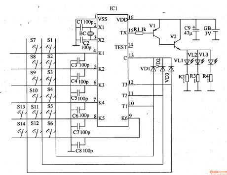
The remote control e-hoist circuit (1)
Published:2011/7/22 20:13:00 Author:qqtang | Keyword: remote control, e-hoist circuit


The infrared emitter circuit consists of the infrared emitter encoding integrated circuit IC1 and the external elements, see as figure 8-113. The control key S1-S4, diode VDl-VD3, capacitor C3-C8 and 4-13 pin of IC1 compose the key control input circuit; the capacitors of C1 and C2, quartz crystal oscillator BC and the 2- and 3-pin of IC1 compose the oscillator circuit; the resistor Rl-R4, transistors of V1 and V2, infrared LED VL1-VL3 and 15-pin of IC1 compose the infrared drive circuit.
(View)
View full Circuit Diagram | Comments | Reading(1550)
The car back-up alarm (1)
Published:2011/7/22 9:48:00 Author:qqtang | Keyword: back-up alarm

The working principle of the circuitThe car back-up alarm consists of 6 NOR gate integrated circuit IC(Dl-D6), transistor V, output transistor T and loudspeaker BL,etc, see as figure 7-121.
The internal NOR gates of D1-D6 of the IC, the external resistors of R3 and R7 and the capacitors of C3 and C2 compose the audio oscillator, which is used generate the basic frequency of the alarm sound. By changing the volumes of C2 and C3, the tone can be changed. (View)
View full Circuit Diagram | Comments | Reading(1544)
The automobile burglarproof alarm (3)
Published:2011/7/23 3:30:00 Author:qqtang | Keyword: burglarproof alarm

The working principle of the circuit The burglarproof alarm circuit consists of the time-based integrated circuit IC, high power switch tube V, switch S2, time delay capacitor C and resistors R1-R4, see as figure 7-81.
Sl(Sla and Slb) is the igniting switch (car lock switch), GB is the storage battery of the car, R4 is the additional current limit resistor of the igniting coil.When the car starts normally, the switch S2 is at the point of b, the burglarproof circuit is not working. (View)
View full Circuit Diagram | Comments | Reading(508)
The automobile burglarproof alarm (4)
Published:2011/7/23 3:36:00 Author:qqtang | Keyword: burglarproof alarm

The working principle of the circuit The burglarproof alarm circuit consists of the trigger control circuit and sound alarm circuit, see as figure 7-82.
The trigger control circuit consists of the igniting switch S1, alarm control switch S2, resistors R3-R5, capacitors of C2 and C3, regulated diode VS, diodes of VD1 and VD2, transistors of V3 and V4. The sound alarm circuit consists of the resistor R1, capacitor C1, thyristor VT, transistors of V1 and V2, audio circuit IC and loudspeaker BL. (View)
View full Circuit Diagram | Comments | Reading(412)
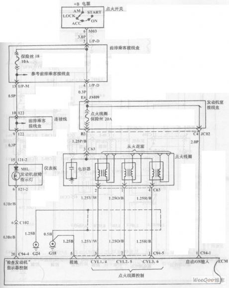
Fuel Injection System Circuit of Hyundai Sonata with V4 Cylinder Engine (9)
Published:2011/7/18 3:27:00 Author:Sue | Keyword: Fuel Injection, Hyundai Sonata, V4 Cylinder

The picture shows the fuel injection system circuit of Hyundai Sonata with V4 cylinder engine. (View)
View full Circuit Diagram | Comments | Reading(787)
Computer motherboard circuit 810 2_17
Published:2011/7/27 1:20:00 Author:Ecco | Keyword: Computer motherboard
View full Circuit Diagram | Comments | Reading(567)
Computer motherboard circuit 810 2_16
Published:2011/7/27 1:19:00 Author:Ecco | Keyword: Computer motherboard
View full Circuit Diagram | Comments | Reading(664)
Computer motherboard circuit 810 2_15
Published:2011/7/27 1:19:00 Author:Ecco | Keyword: Computer motherboard
View full Circuit Diagram | Comments | Reading(575)
Computer motherboard circuit 810 2_14
Published:2011/7/27 1:14:00 Author:Ecco | Keyword: Computer motherboard
View full Circuit Diagram | Comments | Reading(570)
Motorcycle Charging Circuit
Published:2011/7/14 6:05:00 Author:Sue | Keyword: Motorcycle, Charging

When it is being charged, the voltage will rise from 37.9v to 44.4v. (View)
View full Circuit Diagram | Comments | Reading(1052)
The ultrasonic back-up crashproof alarm (1)
Published:2011/7/22 22:36:00 Author:qqtang | Keyword: ultrasonic, crashproof alarm

Here is to introduce an ultrasonic back-up crashproof alarm which is installed in the tail of the car, it detects and alarms with the reflected ultrasonic of the obstacle behind the car, when it has detected the obstacle in the effective range, it will remind the drive.The working principle of the circuit The ultrasonic back-up crashproof alarm consists of the ultrasonic oscillator, ultrasonic emitter/receiver control circuit and acousto-optic alarm circuit, see as figure 7-107.
(View)
View full Circuit Diagram | Comments | Reading(455)
Wide Input Range Voltage Stabilizing Circuit
Published:2011/7/18 6:08:00 Author:Sue | Keyword: Wide, Input Range, Voltage Stabilizing

Figure 9 application circuit 2 (View)
View full Circuit Diagram | Comments | Reading(871)
The automobile burglarproof alarm (5)
Published:2011/7/23 3:47:00 Author:qqtang | Keyword: burglarproof alarm

The working principle of the circuitThe burglarproof alarm circuit consists of the sound control circuit, cutting off trigger/self-lock switch circuit, regulated circuit and alarm circuit, see as figure 7-83.
The sound control circuit consists of the microphone BM, piezoelectric pottery BC, resistors R1-R5, potentiometers RP1-RP4, capacitors C1-C5, transistors V1-V3 and the FET VF. The cutting off trigger/self-lock switch circuit consists of the resistor RIO, short alarm line W, relay K and thyristor (VT1, TV2). (View)
View full Circuit Diagram | Comments | Reading(407)
High Efficiency Charging Circuit
Published:2011/7/18 7:29:00 Author:Sue | Keyword: High Efficiency, Charging

The circuit can be used in power range of 5W-150W(some components have to be adjusted). When it's between 5W-25W, there is no need to put any radiatoron the switch tube.
The circuit is assumed to be used in laptop adapter. It can also be used in electric bicycle's charger and mobile phone's charger. (View)
View full Circuit Diagram | Comments | Reading(883)
3000VA Inverter Power Circuit
Published:2011/7/14 7:12:00 Author:Sue | Keyword: 3000VA, Inverter
View full Circuit Diagram | Comments | Reading(3688)
12V Direct Current Fluorescent Lamp Circuit
Published:2011/7/15 6:02:00 Author:Sue | Keyword: Direct Current, Fluorescent Lamp
View full Circuit Diagram | Comments | Reading(2409)
ATX Power Circuit
Published:2011/7/15 5:56:00 Author:Sue | Keyword: Power
View full Circuit Diagram | Comments | Reading(1855)
| Pages:1457/2234 At 2014411442144314441445144614471448144914501451145214531454145514561457145814591460Under 20 |
Circuit Categories
power supply circuit
Amplifier Circuit
Basic Circuit
LED and Light Circuit
Sensor Circuit
Signal Processing
Electrical Equipment Circuit
Control Circuit
Remote Control Circuit
A/D-D/A Converter Circuit
Audio Circuit
Measuring and Test Circuit
Communication Circuit
Computer-Related Circuit
555 Circuit
Automotive Circuit
Repairing Circuit


