Remote Control Circuit
The remote control e-hoist circuit (1)
Published:2011/7/22 20:13:00 Author:qqtang | Keyword: remote control, e-hoist circuit | From:SeekIC


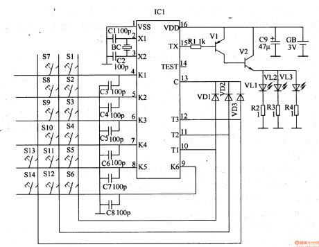
The infrared emitter circuit consists of the infrared emitter encoding integrated circuit IC1 and the external elements, see as figure 8-113. The control key S1-S4, diode VDl-VD3, capacitor C3-C8 and 4-13 pin of IC1 compose the key control input circuit; the capacitors of C1 and C2, quartz crystal oscillator BC and the 2- and 3-pin of IC1 compose the oscillator circuit; the resistor Rl-R4, transistors of V1 and V2, infrared LED VL1-VL3 and 15-pin of IC1 compose the infrared drive circuit.
Reprinted Url Of This Article:
http://www.seekic.com/circuit_diagram/Remote_Control_Circuit/The_remote_control_e_hoist_circuit_1.html
Print this Page | Comments | Reading(3)

Article Categories
power supply circuit
Amplifier Circuit
Basic Circuit
LED and Light Circuit
Sensor Circuit
Signal Processing
Electrical Equipment Circuit
Control Circuit
Remote Control Circuit
A/D-D/A Converter Circuit
Audio Circuit
Measuring and Test Circuit
Communication Circuit
Computer-Related Circuit
555 Circuit
Automotive Circuit
Repairing Circuit
Code: