About SeekIC | Services | Payment | Advertisements service | Contact Us | Links
© 2008-2012 SeekIC.com Corp.All Rights Reserved.

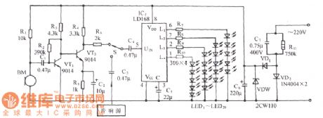
Published:2014/3/10 21:49:00 Author:lynne | Keyword: LD168 audio voltage-controlled Carla OK lights shine control circuit diagram, LD168
The circuit shown in the figure, the voltage-controlled flash it to an audio tape recorders ASIC LD168 is the core component, it is through an external SCR drive four lights. (View)
View full Circuit Diagram | Comments | Reading(2255)
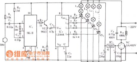
Published:2014/3/10 21:47:00 Author:lynne | Keyword: LD168 audio voltage-controlled flash decoration control circuit diagram, LD168
Figure, LD168 is an indication for ASIC sound level for tape recorders flash speakers. It has four outputs can directly drive a plurality of light emitting diodes, thyristor devices can also be driven by the drive lantern light. (View)
View full Circuit Diagram | Comments | Reading(1497)
Published:2014/3/10 21:42:00 Author:lynne | Keyword: Adopts SH805 acousto-optic double control power lights with birdsong circuit diagram, SH805
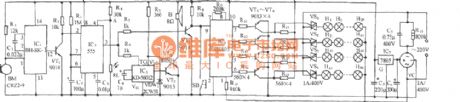
Circuit is shown, which consists of voice circuits, sound, light and dual control one-shot timer circuit, SH805 light control circuit, birds sound buck rectifier circuit and the AC circuit. It achieved manually or automatically controlled four-power lights, there are 16 kinds of lights transform patterns, but also issued sweet birdsong. BM is the acoustic energy sensor; BH-SK-I is the voice ASIC. (View)
View full Circuit Diagram | Comments | Reading(2090)
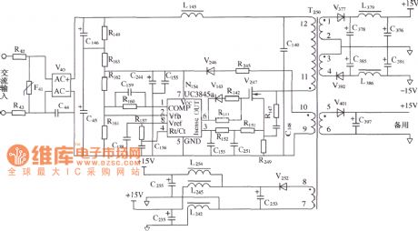
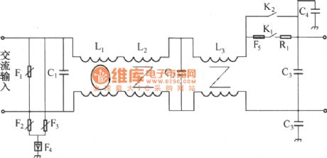
Published:2014/3/10 21:38:00 Author:lynne | Keyword: BBK switching power supply diagram,
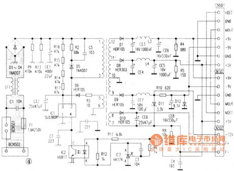
BBK switching power supply diagram shown as figure:
(View)
View full Circuit Diagram | Comments | Reading(1855)
Published:2014/3/10 21:34:00 Author:lynne | Keyword: 5GM168 audio voltage controlled style dance hall lanterns decorated with birds sound Diagram, 5GM168
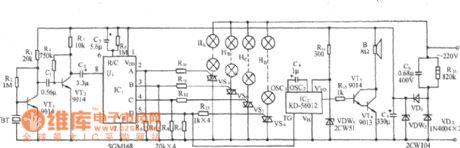
As shown, it is based on a voltage-controlled lantern audio control IC 5GM168 as the core, with the sound of birds and the sound amplifier circuit, consisting of a voltage-controlled lights and birdsong audio sound circuitry. (View)
View full Circuit Diagram | Comments | Reading(2132)
Published:2014/3/9 22:50:00 Author: | Keyword: The DMA auxiliary power circuit diagram,
View full Circuit Diagram | Comments | Reading(1780)
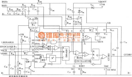
Published:2014/3/9 22:49:00 Author: | Keyword: The DMA booster/power factor correction control circuit diagram,
View full Circuit Diagram | Comments | Reading(1484)
Published:2014/3/9 22:46:00 Author: | Keyword: Amoi A8 + - LCD circuit principle diagram,
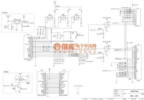
Amoi A8 + as shown - LCD circuit principle diagram (View)
View full Circuit Diagram | Comments | Reading(1659)
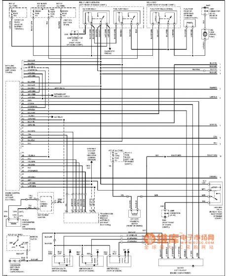
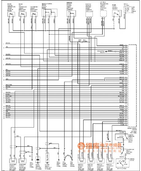
Published:2014/3/9 22:45:00 Author: | Keyword: Mazda 929 cars automatic air conditioning air conditioning system circuit diagram,
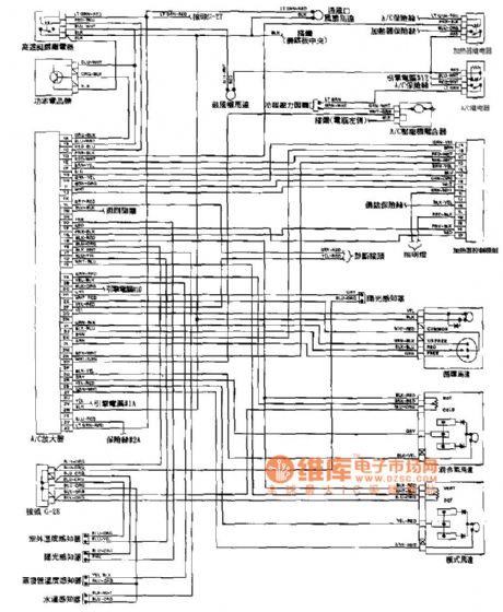
Mazda 929 cars as shown automatic air conditioning air conditioning system circuit diagram (View)
View full Circuit Diagram | Comments | Reading(2598)
Published:2014/3/9 22:45:00 Author: | Keyword: The DMA lossless absorption buffer circuit diagram,
View full Circuit Diagram | Comments | Reading(1455)
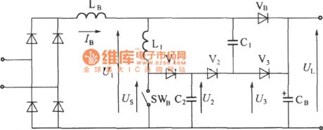
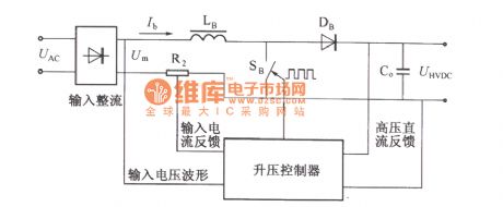
Published:2014/3/9 22:44:00 Author: | Keyword: Booster type power factor correction principle of electric circuit diagram,
View full Circuit Diagram | Comments | Reading(1370)
Published:2014/3/9 22:41:00 Author: | Keyword: Amoi A8 + - IO mouth - SIM card schematic circuit diagram,
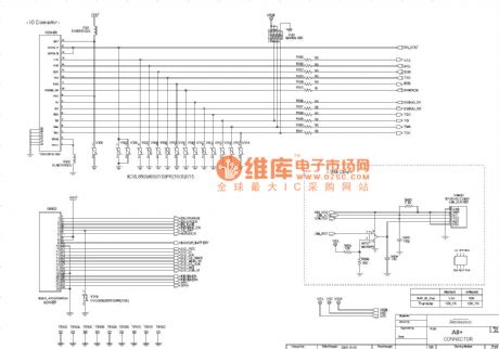
Amoi A8 + as shown - IO mouth - SIM card schematic circuit diagram (View)
View full Circuit Diagram | Comments | Reading(1625)
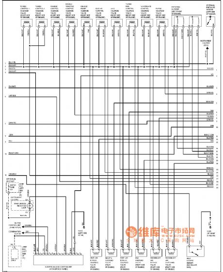
Published:2014/3/9 22:38:00 Author: | Keyword: Mazda engine performance diagram (1.3 L),
Mazda engine performance diagram as shown (1.3 L) (View)
View full Circuit Diagram | Comments | Reading(1627)
Published:2014/3/9 22:36:00 Author: | Keyword: Amoi A8 + - 16 chord and logic circuit principle diagram,
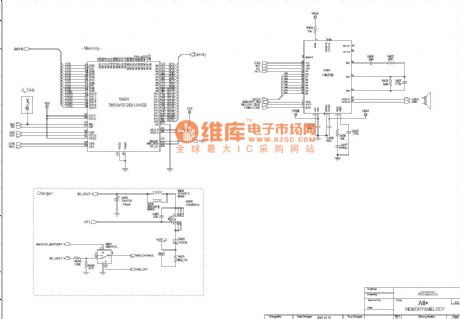
Amoi A8 + as shown - 16 chord and logic circuit principle diagram (View)
View full Circuit Diagram | Comments | Reading(1283)
Published:2014/3/9 22:34:00 Author: | Keyword: DMAl2 input circuit diagram,
View full Circuit Diagram | Comments | Reading(1269)
Published:2014/3/9 22:29:00 Author: | Keyword: mazda 发动机性能电路图(1.3L) 二,
Mazda engine performance diagram as shown (1.3 L) (View)
View full Circuit Diagram | Comments | Reading(907)
Published:2014/3/9 22:26:00 Author: | Keyword: Mazda engine performance diagram (1.3 L) three,

Mazda engine performance diagram as shown (1.3 L) three (View)
View full Circuit Diagram | Comments | Reading(1830)
Published:2014/3/9 21:33:00 Author:lynne | Keyword: Sound control water lantern with broadcasting some great musical compositions circuit diagram(5G167) schematic, 5G167
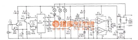
The circuit shown in the figure, which consists of acoustic / electric sensors, audio amplifiers, circulators count pulse distribution / driver circuit, SCR control circuit, vocal music circuit, audio amplifier circuit and the AC buck rectifier circuit. IC1 using 5G167, which is dedicated to rotating ring counts recorders allocation flash tank design / driver integrated circuit, which contains the rectified signal amplifiers, voltage-controlled oscillator and three ring timing counter and three drain output circuit. (View)
View full Circuit Diagram | Comments | Reading(2037)
Published:2014/3/9 21:34:00 Author:lynne | Keyword: La1-xSrxFeO3,the equivalent circuit diagram of the transducer, La1-xSrxFeO3
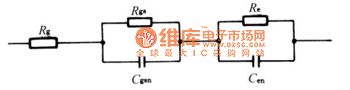
Figure: Rg-grain resistance, Rgs grain surface resistance, Cgsn grain surface non-Debye capacitive, Re-electrode surface resistance, Cen-electrode surface 'non Debye capacitor.
(View)
View full Circuit Diagram | Comments | Reading(1590)
Published:2014/3/9 21:37:00 Author:lynne | Keyword: 5G167 voltage-controlled two-way audio water lantern control circuit diagram, 5G167
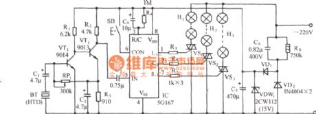
As shown in the circuit, 5G167 is Shanghai components Wuchang tape recorders manufactured rotary speaker ASIC lighting control; HTD is to convert the audio signal into a corresponding electrical signal. (View)
View full Circuit Diagram | Comments | Reading(2042)
| Pages:14/2234 1234567891011121314151617181920Under 20 |
Response in 12 hours
© 2008-2012 SeekIC.com Corp.All Rights Reserved.