
Index 87
PROTECTED_OUTPUT_STAGE
Published:2009/7/19 23:32:00 Author:Jessie
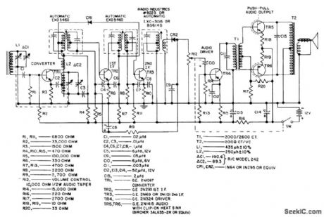
High-voltage passivated mesa transistor in output stage of Japanese home radio is protected by silicon varistor R.-T. Kojima and M. Watanabe, When You're Second, You Try Harder, Electronics, 38:25, p 81-89. (View)
View full Circuit Diagram | Comments | Reading(578)
SIX_TRANSISTOR_72_V_1_W_BROADCAST
Published:2009/7/19 23:29:00 Author:Jessie
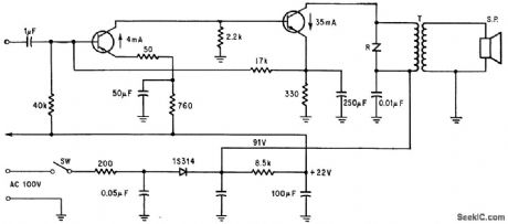
Nominal sensitivity is 150 microvolts per meter. Zero-signal battery drain is 10 ma.- Transistor Manual, Seventh Edition, General Electric Co., 1964, p 293. (View)
View full Circuit Diagram | Comments | Reading(483)
BALANCED_TMO_VCO
Published:2009/7/10 0:23:00 Author:May


This TMOS VCO operates in push-pull to produce 4 W at 70 MHz. It consists of two MFE930 TMOS devices in a balanced VCO that generally provide better linearity than the single-ended types. Varactors are not used because the design takes advantage of the large change in Miller capacitance, CRSS, that is available in TMOS gate structures.In the balanced VCO, the fundamental (fo) and/or twice the fundamental (2fo) can be coupled from the circuit at separate nodes. This makes the balanced oscillator very useful in phase-locked loops. The fundamental: (View)
View full Circuit Diagram | Comments | Reading(592)
FM_IF_gain_block_with_voltage_regulator
Published:2009/7/20 2:44:00 Author:Jessie
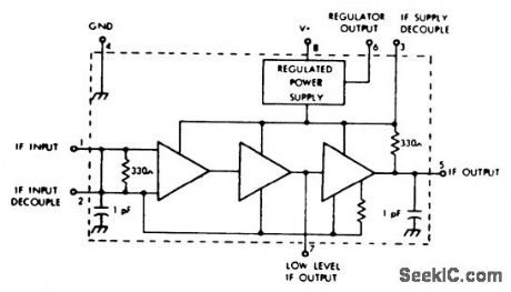
FM IF gain block with voltage regulator. The gain at 10.7 MHz is typically 35 dB.Operating voltage range is 10 to 20 volts. The internal voltage regulator regulates at 7.7 volts and is for external use (courtesy GTE Sylvania Incorporated). (View)
View full Circuit Diagram | Comments | Reading(575)
AM_front_end_with_AM_FM_IF_amplifier_and_detector
Published:2009/7/20 2:32:00 Author:Jessie
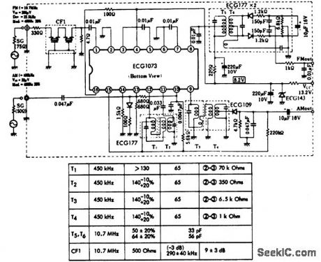
AM front end with AM/FMIF amplifier and detector.ince supply voltage is 13.2 volts,he circuit is ideal for automotive applications.F1 is a 10.7 MHz ceramic filter(courtesy GTE Sylvania Incorporated). (View)
View full Circuit Diagram | Comments | Reading(801)
The 300W electric transformer made of IR2151 and IR840
Published:2011/7/21 0:48:00 Author:Borg | Keyword: electric transformer
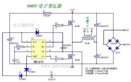
The 300W electric transformer is made of IR2151 and IR840.This transformer can work normally without regulation.
(View)
View full Circuit Diagram | Comments | Reading(6009)
AM_FM_IF_amplifier_and_detector_with_tuning_meter
Published:2009/7/20 2:29:00 Author:Jessie
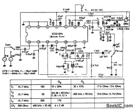
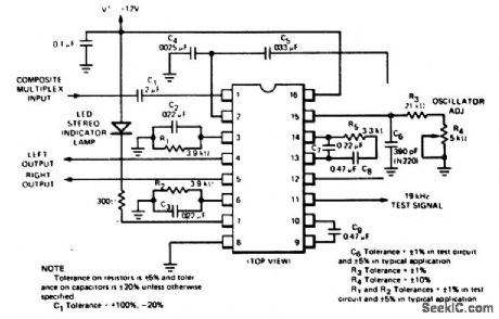
AM/FM IF amplifier and detector with tuning meter.AF output is about 10 mV for 400-hertz modulation at 30%.Typical voltage gain is 90 dB for FM and 80 dB for AM(courtesy GTE Sylvania Incorporated). (View)
View full Circuit Diagram | Comments | Reading(941)
AM_broadcast_receiver_using_an_ECG787_16_pin_DIP
Published:2009/7/20 2:22:00 Author:Jessie
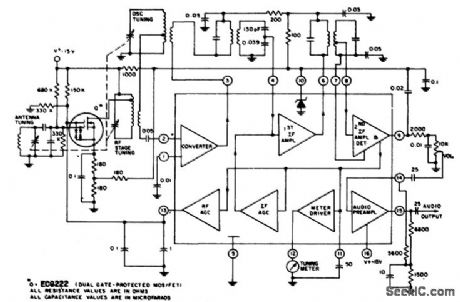
AM broadcast receiver using an ECG787 16-pin DIP.The RF stage is optional,Coils and tuning capacitor can be salvaged from a junk transistor radio or purchased at Radio Shack,The ECG787 provides 75 mV of audio output at the detector that can be fed to any of the audio amplifier circuits shown in this volume,above(courtesy GTE Sylvania Incorporated).PLL FM stereo multiplex decoder using an ECG743 16-pin DIP.The ECG743 features 45 dB channel separation,automatic stereo/mono switching,stereo indicator lamp driver with current limiting,high impedance input with low-impedance output,70 dB SCA rejection and one adjustment alignment.Supply voltage rang is 10 to 16 volts. This circuit is suitable for line-operated and automotive FM stereo receivers below(courtesy GTE Sylvania Incorporated). (View)
View full Circuit Diagram | Comments | Reading(589)
AM_FM_IF_amplifier_for_455_kHz_and_107_MHz_using_an_ECG1054_14_pin_DIP
Published:2009/7/20 2:20:00 Author:Jessie
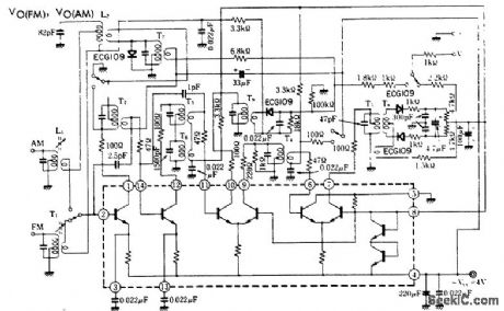
AM/FM IF amplifier for 455 kHz and 10.7 MHz using an ECG1054 14-pin DIP. IF coils and transformers are all standard and can be purchased at Radio Shack. Supply voltage is 4 volts (courtesy GTE Sylvania Incorporated). (View)
View full Circuit Diagram | Comments | Reading(627)
AM_broadcast_receiver_using_an_LM3909_chip
Published:2009/7/20 2:19:00 Author:Jessie
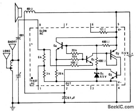
AM broadcast receiver using an LM3909 chip. The LM3909 acts as a detector amplifier. It does not oscillate because there is no positive feedback. The receiver is only good for local stations and sensitivity is similar to a crystal set. It will drive a 6-inch loudspeaker. The antenna can be the short version shown, which is 10 to 20 feet long, or the long version, which is 30 to 100 feet. The long one works better (courtesy National Semiconductor Corporation). (View)
View full Circuit Diagram | Comments | Reading(482)
FM_stereo_multiplex_decoder_using_an_ECG789_16_pin_QIP
Published:2009/7/20 2:17:00 Author:Jessie
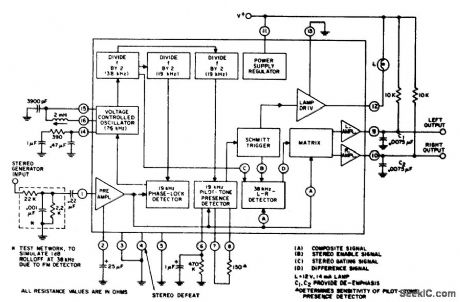
FM stereo multiplex decoder using an ECG789 16-pin QIP. Typical supply voltage is 12 volts; however, the ECG789 can operate over a wide variation of supply voltage up to 16 volts. The internal lamp driver can be made to drive a lamp of hjgher power than the 14 mA one shown by controlling an external NPN or PNP transistor. To drive PNP type, pin 13 is grounded and pin 12 is connected to the base. To drive an NPN type, pin 12 is connected to supply and pin 13 is connected to the base (courtesy GTE Sylvania Incorporated). (View)
View full Circuit Diagram | Comments | Reading(978)
Complete_107_MHz_FM_IF_system_for_FM_broadcast_receivers_using_an_ECG788_16_pin_DIP
Published:2009/7/20 2:15:00 Author:Jessie
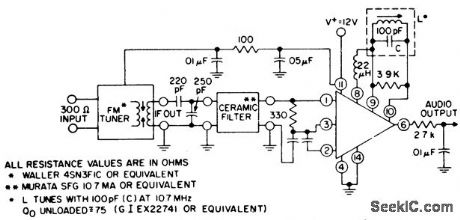
Complete 10.7 MHz FM IF system for FM broadcast receivers using an ECG788 16-pin DIP. The ECG788 chip also has delayed AGC at pin 15 for an RF amplifier, a tuning meter output at pin 13, a mute drive at pin 12, muting sensitivity at pin 5 and an AFC output at pin 7 (courtesy GTE Sylvania Incorporated). (View)
View full Circuit Diagram | Comments | Reading(709)
IF_amplifier_for_455_kHz_or_107_MHz
Published:2009/7/20 2:15:00 Author:Jessie
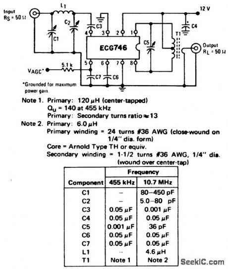
IF amplifier for 455 kHz or 10.7 MHz. See table for component selection (courtesy GTE Sylvania Incorporated). (View)
View full Circuit Diagram | Comments | Reading(705)
AM_broadcast_tuner_with_BF_amplifier
Published:2009/7/20 2:13:00 Author:Jessie
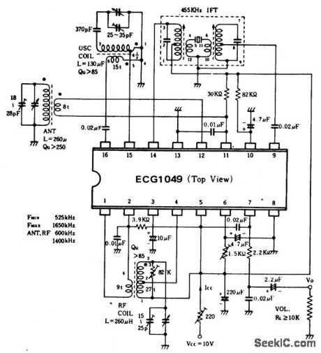
AM broadcast tuner with BF amplifier.All coils and transformers are standard and can be purchased at Radio Shack.The three-section tuning capacitor is also standard.Audio output with 400-hertz modulation at 30% is 80 mV(courtesy GTE Sylvania Incorporated). (View)
View full Circuit Diagram | Comments | Reading(674)
107_MHz_FM_wide_band_high_gain_IF_amplifier_limiter_using_an_ECG781_8_lead_TO_99
Published:2009/7/20 2:12:00 Author:Jessie
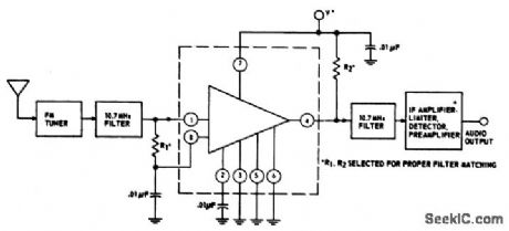
10.7 MHz FM wide-band high-gain IF amplifier-limiter using an ECG781 8-lead TO-99. Supply voltage is 8.5 volts. The circuit provides a voltage gain of 80 dB. Typical sensitivity is 50,mV at 10.7 MHz (courtesy GTE Sylvania Incorporated). (View)
View full Circuit Diagram | Comments | Reading(495)
VARYING_FREQUENCY_OSCILLATOR
Published:2009/7/9 23:29:00 Author:May
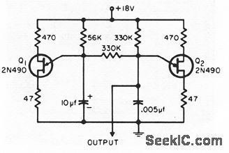
Output frequency of alarm tone generator changes continuously. With suitable ampliler and loudspeaker, can easily be heard in noisy environments where single tone or amplitudemodulated tone would go unnoticed.-A. Jnall, Varying-Frequency Warning Alarm, EEE, l2:7, p 25. (View)
View full Circuit Diagram | Comments | Reading(656)
Smith_AFC_system_for_an_FM_receiver
Published:2009/7/20 2:10:00 Author:Jessie
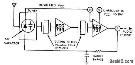
Smith AFC system for an FM receiver. The ECG737 is an FM detector and limiter. It uses quadrature detection and includes a voltage regulator at pin 3. The ECG734 is an FM gain block. This type of circuit is ideal for FM mobile operation (courtesy GTE Sylvania Incorporated). (View)
View full Circuit Diagram | Comments | Reading(616)
AM_broadcast_tuner_with_two_IF_amplifiers
Published:2009/7/20 2:09:00 Author:Jessie
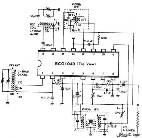
AM broadcast tuner with two IF amplifiers. Audio output with 400-hertz modulation at 30% is 80 mV. All coils, transformers and variable capacitors are standard.The tuning capacitor is a two-section type with the antenna section at 18 to 28 pF and trimmed and the oscillator section at 25 to 35 pF and trimmed. Pads can be purchased at Radio Shack (courtesy GTE Sylvania Incorporated). (View)
View full Circuit Diagram | Comments | Reading(580)
VARIABLE_AMPLITUDE_TUNNEL_DIODE_OSCILLATOR
Published:2009/7/20 2:07:00 Author:Jessie
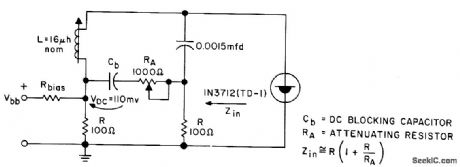
Attenuating resistor RA varies magnitude of oscillator swing, so oscillator operates over limited highly linear portion of diode conductance curve.- Transistor Manual, Seventh Edition, General Electric Co., 1964, p 351. (View)
View full Circuit Diagram | Comments | Reading(828)
SINE_WAVE_TUNNEL_DIODE_1
Published:2009/7/20 2:05:00 Author:Jessie
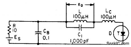
Series filter selects desired frequency and rejects harmonics from pulse-shaped output of basic tunnel-diode relaxation oscillator. Values shown give 0.45 Mc, constant within 0.05 Mc over bias range of 100 to 400 mv.-Wen-Hsiung Ko, Designing Tunnel Diode Oscillators, Electronics, 34:6, p 68-72. (View)
View full Circuit Diagram | Comments | Reading(693)
| Pages:87/195 At 2081828384858687888990919293949596979899100Under 20 |
Circuit Categories
power supply circuit
Amplifier Circuit
Basic Circuit
LED and Light Circuit
Sensor Circuit
Signal Processing
Electrical Equipment Circuit
Control Circuit
Remote Control Circuit
A/D-D/A Converter Circuit
Audio Circuit
Measuring and Test Circuit
Communication Circuit
Computer-Related Circuit
555 Circuit
Automotive Circuit
Repairing Circuit