
Function Signal Generator
Index 2
Atlantis electromagnetic cooker circuit
Published:2011/6/5 22:11:00 Author:John | Keyword: electromagnetic cooker
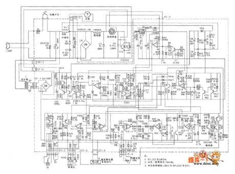
Atlantis electromagnetic cooker circuit is shown in the following.
(View)
View full Circuit Diagram | Comments | Reading(1158)
Panasonic induction cooker circuit (KY-P2N)
Published:2011/6/6 23:41:00 Author:John | Keyword: induction cooker
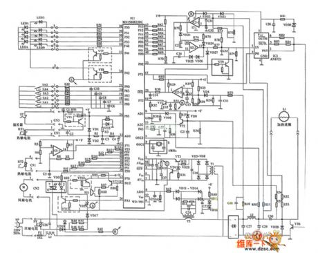
Panasonic induction cooker circuit (KY-P2N) is shown below.
(View)
View full Circuit Diagram | Comments | Reading(1748)
Microwave circuit
Published:2011/5/23 23:28:00 Author:John | Keyword: Microwave
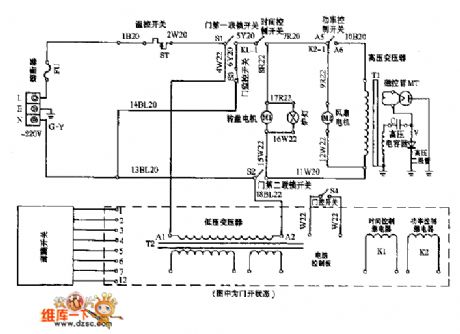
Microwave circuit is shown below.
(View)
View full Circuit Diagram | Comments | Reading(1446)
Sterilizer electronic control circuit
Published:2011/5/15 1:44:00 Author:John | Keyword: Sterilizer
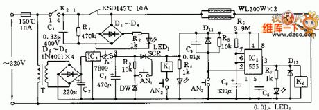
The sterilizer makes the use of infrared heating circuit theory. The sterilizer creates a high-temperature situation in a closed cabinet, when it is used for tableware disinfection. Its circuit is shown below.
Electric control circuit includes the AC step-down voltage regulator circuit, infrared heating circuit and timing control circuit and so forth. Single-phase AC power is transmitted from temperature limit fuses FU (10A, 150 ℃) to the primary transformer T. Then, the AC power is through the processing of step-down, rectifier and regulator. The output DC voltage achieves 9V. Such voltage would get to the anode of a single SCR through the normally closed contacts K1 (1-3). (View)
View full Circuit Diagram | Comments | Reading(1058)
remote-control fan circuit
Published:2011/5/17 5:11:00 Author:chopper | Keyword: remote-control fan

View full Circuit Diagram | Comments | Reading(916)
The function generator composed of 555 timer
Published:2011/4/18 21:04:00 Author:Ecco | Keyword: function generator , 555 , timer

The chart shows a function generator circuit composed of 555 timer. The circuit consists of a CH7555 timer and some transistors and RC components. It can generate triangle wave, square wave, sine wave, sawtooth and square wave sweep simultaneously. Ramp can be positive or negative. The frequency of various waveforms is adjustable from 0.1Hz ~ 100kHz, the amplitude of square wave is 5 ~ 15V, it can directly drive TTL circuits (power supply is 5V). Nonlinear ramp is below 1%, sine wave distortion is less than 3%.
(View)
View full Circuit Diagram | Comments | Reading(6420)
5Hz ~ 5MHz function generator composed of MAX038
Published:2011/4/18 20:17:00 Author:Ecco | Keyword: 5Hz ~ 5MHz , function generator

The 5Hz ~ 5MHz function generator circuit is shown in the chart. The circuit is a 5Hz ~ 5MHz function generator circuit, which could output the square wave, sine wave and triangular wave according to the need. The integrated circuit MAX038 is a special function generator which sets the oscillation frequency by the current of the input current terminal IIN. It changes the reference voltage into current by a resistor, the current flowing the end of FADJ is used to adjust the frequency. The frequency range of the circuit is set as multiples of 10. The timing capacitor is changed in the range of 75pF ~ 10μF. As the wire connection has an effect on working capacitor when the frequency is 5MHz, it could increase a CTc variable condenser in 50pF connecting to 75pF working capacitor in parallel, and it is easy to correct the high frequency. Frequency setting potentiometer PR1 adopts a resistor with 10 laps. The circuit is characterized by simple structure, adjustable components, reliable working.
(View)
View full Circuit Diagram | Comments | Reading(9444)
The function generator using 8038
Published:2011/4/18 20:16:00 Author:Ecco | Keyword: function generator
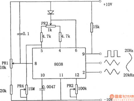
The function generator using 8038 is shown in the chart. The function generator using integrated circuit chip 8038 can get square, triangle wave and sine wave simultaneously. Triangular wave is directly formed by discharging from the constant capacitor; square wave received by the controlling signal; sine wave received by the triangular wave passing the approximation circuit. The sine curve obtained like this is not a smooth sine curve, and the distortion is about 1% and it can meet the needs of general purpose. The potentiometer PR1 in the circuit is used to adjust the frequency, its range is in 20Hz to 20kHz. PR2 is used to adjust the waveform distortion, PR3 is used to adjust the duty cycle of the waveform.
(View)
View full Circuit Diagram | Comments | Reading(7290)
General-purpose function generator
Published:2011/4/17 20:52:00 Author:Ecco | Keyword: general-purpose , function generator
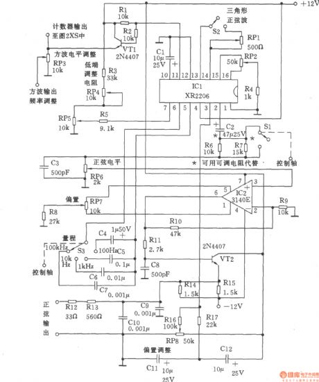
Signal generator can be divided into three parts: the sine wave and triangle wave generator, counter and pulse and ramp generator. The circuit is as shown, XR2206 adopts voltage controlled oscillator, the frequency adjustment is achieved by potentiometer RP5 (10k), it is easy to adjust to the frequency in one-thousandth. If you change the resistance of the fixed resistor R3, the resistance of the RP5 could also be changed. Sine and triangular waves is different from other similar instruments, the attenuator switch Sl only can change the magnitude of signal, it does not affect the bias voltage. According to the need, the fixed attenuation can be got (to 20dB, the voltage ratio is 10), it adjusted by R6, fixed resistor R7 connecting in parallel. It also could connect to rheostat to adjust resistance. Although the adjustment of resistance is more expensive, but it is easy to implement.
(View)
View full Circuit Diagram | Comments | Reading(3539)
The stable function generator
Published:2011/4/14 2:32:00 Author:Ecco | Keyword: stable, function generator
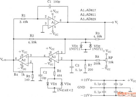
This circuit is a function generator, as shown. Its square-wave output has a short rise time and the amplitude is not sensitive to temperature; In addition,thetriangular output waveform changesat the exactlysame rate in the whole range.
(View)
View full Circuit Diagram | Comments | Reading(839)
| Pages:2/2 12 |
Circuit Categories
power supply circuit
Amplifier Circuit
Basic Circuit
LED and Light Circuit
Sensor Circuit
Signal Processing
Electrical Equipment Circuit
Control Circuit
Remote Control Circuit
A/D-D/A Converter Circuit
Audio Circuit
Measuring and Test Circuit
Communication Circuit
Computer-Related Circuit
555 Circuit
Automotive Circuit
Repairing Circuit