Sensor Circuit
Index 19
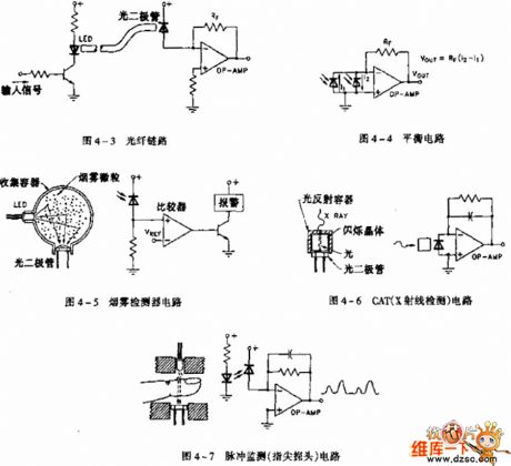
light sensor application circuit diagram
Published:2011/6/18 9:56:00 Author:Nancy | Keyword: light sensor
View full Circuit Diagram | Comments | Reading(865)
Temperature-Sensitive Diode Application Circuit
Published:2011/7/10 2:47:00 Author:Robert | Keyword: Temperature-Sensitive Diode, Application
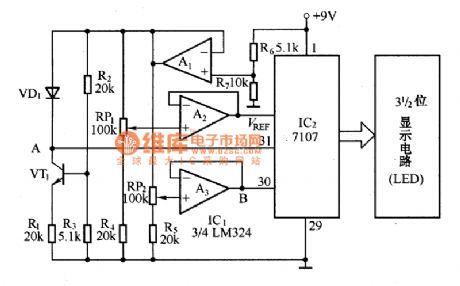
The circuit shown in the picture is the digital temperature meter circuit which uses temperature-sensitive diode as the temperature-measurement element. It is mainly made up of the A/D converter 7107, operational amplifier LM324, 3-digit LED display circuit and temperature-sensitive diode and so on. It features high accuracy, good stability, versatility, ease of use and so on. Its temperature measurement range is 0℃~100℃ with accuracy ±1℃.
The voltage follower, which is made up of the operational amplifier A1, supply power for the A/D converter integrated circuit IC2 and the temperature sampling circuit separately to reduce the interaction between them. The semiconductor transistor VT1 and R1, R2, R3 supply stable bias current for the temperature-sensitive diode VD1. (View)
View full Circuit Diagram | Comments | Reading(2000)
Metal Foil Resistance Strain Gauge Basic Structure Circuit
Published:2011/7/10 7:17:00 Author:Robert | Keyword: Metal, Foil, Resistance, Strain, Gauge, Structure
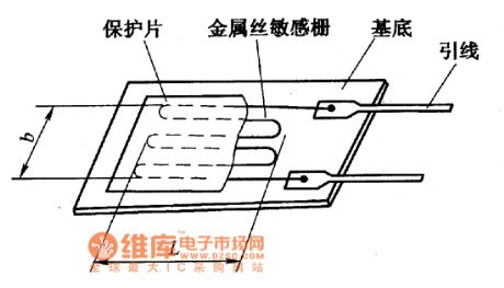
The picture shows the metal foil resistance strain gauge basic structure circuit. (View)
View full Circuit Diagram | Comments | Reading(1073)
QM Series Gas Sensor Shape Circuit
Published:2011/7/3 5:50:00 Author:Robert | Keyword: Gas, Sensor, Shape
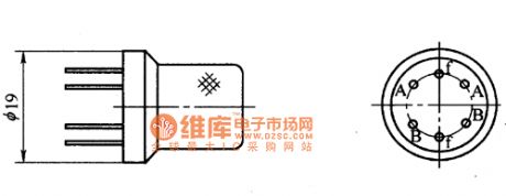
The picture shows the QM series gas sensor shape. (View)
View full Circuit Diagram | Comments | Reading(812)
QM Series Gas Sensor Basic Testing Circuit
Published:2011/7/3 5:51:00 Author:Robert | Keyword: Gas, Sensor, Basic, Testing
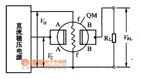
The picture shows the QM series gas sensor basic testing circuit. (View)
View full Circuit Diagram | Comments | Reading(954)
3ACM And 3BCM Type Magnetic Transistor Shape Circuit
Published:2011/7/3 9:10:00 Author:Robert | Keyword: Magnetic, Transistor, Shape
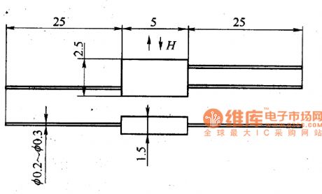
The picture shows the 3ACM and 3BCM type magnetic transistor shape circuit. (View)
View full Circuit Diagram | Comments | Reading(1116)
VR-tube High Frequency Signal Generator Circuit
Published:2011/6/30 2:51:00 Author:Joyce | Keyword: VR-tube , High Frequency , Signal , Generator
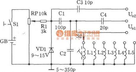
As shown in figure, the circuit uses the characteristic of zener breakdown of the VR-tube to get high frequency signals amounting to hundreds of megahertz. Single frequency signals from the output end V01 can be used to adjust the resonant frequency of the tuning circuits. High frequency signals of broad spectrum from output end V02 can track between the input resonant circuits and the local oscillator tuning circuit of uperheterodyne resonant receiver. The frequency range of the generator is 100kHz ~ 27 MHz, which is divided into five frequency range :100kHz~300kHz~1MHz~3MHz~9MHz~27MHz. (View)
View full Circuit Diagram | Comments | Reading(2066)
High-Frequency-Generating Lamplighter Circuit
Published:2011/6/30 3:21:00 Author:Joyce | Keyword: High-Frequency-Generating , Lamplighter

As shown in the figure is a high-frequency-generating lamplighter circuit. Supplied by battery of 8 V ~ 14 V, it will light 6 W ~ 12 W fluorescent lamps after oscillation. Transistor VT can use low frequency high power transistor like 3DD12A, D3D4D, 3 DD5C and 3 DDl5.When in assembly, aluminum radiator of 70mm×40mm×2mm shall be installed; Small wire-round potentiometer RP would be first choice; High-frequency pulse transformer T can use ferrite cans of 22 mm in diameter. (View)
View full Circuit Diagram | Comments | Reading(1294)
Multiple-frequency Signal Generator Circuit
Published:2011/6/30 3:34:00 Author:Joyce | Keyword: Multiple-frequency , Signal, Generator


As shown in the figure is a multi-frequency signal generator. SJT, VT1 constitute a crystal oscillator. Since quartz crystal SJT is used as an equivalent inductance, which has a high equivalent value Q, other components and stray parameters have little effect on the oscillation frequency, therefore it has a stabile frequency. Source follower is composed of VT2 to get lower output impedance and buffering, so as to avoid effect on the stability of crystal caused by loading. In order to obtain more frequency marks to calibrate the receiver, the following square wave circuit can be used.
(View)
View full Circuit Diagram | Comments | Reading(1161)
Mutiple Waveform Generator Circuit
Published:2011/6/30 3:48:00 Author:Joyce | Keyword: Mutiple , Waveform , Generator

As shown in the figure, the circuit can produce and output square wave, triangle wave and sine wave.It is especially suitable for electronic lovers and students doing experiments with oscilloscopes to observe the signal waveform. This signal generator circuit is simple, low-cost and easy to adjust. 555 timing is connected in a multivibrator form. C2 is a timing capacitance, whose charging loop and discharging loop is R2→R3→RP→C2 and C2→RP→R3→ foot 7 of IC(discharge tube) respectively. Because R3+RP》R2 , the charging time constant and discharging time constant are approximately equal. Output of foot 3 of IC is approximately symmetric square wave. (View)
View full Circuit Diagram | Comments | Reading(3163)
Mutiple Output Crystal Oscillator Circuit
Published:2011/6/30 3:58:00 Author:Joyce | Keyword: Mutiple Output, Crystal, Oscillator

As shown in the figure is a multiple output crystal oscillator. It is mainly composed of 3 gates of Al, four resistances, two capacitances and a piece of crystal. R1 ~ R4 offset two inverters within the linear range, and they are connected between foot 4 and foot 1 of A1 by crystal SJT to provide the feedback loop. It will produce oscillation only on the fundamental frequency of the crystal.
Choice of components: capacitance C1 is 15 p (fine-tuning capacitor). Resistance R1, R3 is 220 Ω, R2 is 560 Ω, R4 is 1.8 k Ω, R5 is 1 kΩ, and the nominal power is 1 / 8 W. Integrated circuit Al is 7404, A2 is 74 LS74, and A3 is 74 LS393. Quartz crystal SJT is SW60A-4096 kHz. Switch SA is KNX (1 x 3). (View)
View full Circuit Diagram | Comments | Reading(1362)
Square Wave and Sine Wave Generator Circuit
Published:2011/6/30 4:08:00 Author:Joyce | Keyword: Square Wave , Sine Wave , Generator

As shown in the figure is a square wave and sine wave generator. A clock generator is composed of an ordinary inverse gate and a few components only, which can output two waveforms of the same frequency at the same time: square wave and sine wave. The oscillator operates well in the frequency range between 100 Hz and 10 MHz. If 74 HCU00 which has no buffering output level is used instead of 74 HC00, it will achieve a better effect. (View)
View full Circuit Diagram | Comments | Reading(4934)
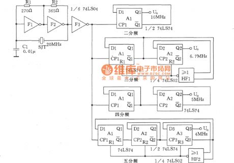
Crystal Oscillator and Frequency Divider Circuit
Published:2011/6/30 4:10:00 Author:Joyce | Keyword: Crystal Oscillator, Frequency Divider
View full Circuit Diagram | Comments | Reading(1626)
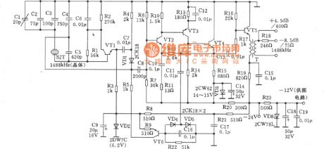
1488kHz Signal Generator and Frequency Divider Circuit
Published:2011/6/30 4:12:00 Author:Joyce | Keyword: 1488kHz, Signal Generator , Frequency Divider
View full Circuit Diagram | Comments | Reading(1055)
Based on BP01 type pressure sensor blood pressure sensor circuit
Published:2011/6/29 0:59:00 Author:Fiona | Keyword: Based on BP01 type pressure sensor
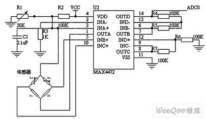
The circuit uses BP01-type pressure sensor and amplifier MAX4472. BP01-type pressure sensor is specifically designed for the detection of blood pressure, and is mainly used for portable electronic device.It uses precision thick-film ceramic chip and nylon plastic packaging,it has the characteristics of a high linear, low noise and external stress of small;it uses the internal calibration and temperature compensation mode to improve the measurement accuracy, stability and repeatability, in the whole range,the precision is ± 1%, zero offset is not greater than ± 300μV.MAX4472 is the MAXIM company's a low power consumption chip which integrates four operational amplifiers.
(View)
View full Circuit Diagram | Comments | Reading(2699)
110V Regulated Power Supply Circuit with Stable Performance
Published:2011/6/30 4:43:00 Author:Joyce | Keyword: 110V , Regulated Power Supply , Stable Performance
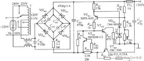
110V regulated power supply circuit with stable performance is as shown in the figure. (View)
View full Circuit Diagram | Comments | Reading(3437)
The finger touch high power sound-light alarm circuit
Published:2011/6/29 21:16:00 Author:Seven | Keyword: finger touch, high power, sound-light alarm
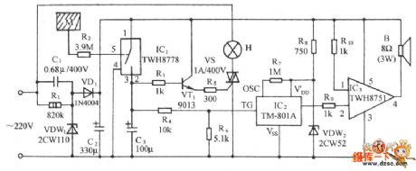
See as the figure, the circuit consists of the touch type power switch, controllable silicon trigger lamp circuit, whistle sound making circuit and audio power amplifier circuit and so on. It can be used in banks and business abodes as the emergency alarm. (View)
View full Circuit Diagram | Comments | Reading(1594)
SWF2 Type Temperature Sensor Circuit
Published:2011/6/28 7:17:00 Author:Robert | Keyword: Temperature, Sensor

The picture shows the SWF2 type temperature sensor circuit. (View)
View full Circuit Diagram | Comments | Reading(884)
Semiconductor Strain Gauge Structure Diagram Circuit
Published:2011/6/23 6:45:00 Author:Robert | Keyword: Semiconductor Strain Gauge, Structure, Diagram
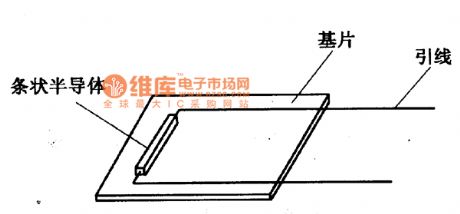
The semiconductor strain gauge is mainly produced by using the piezoresistive effect of the silicon material. If there is the force on the semiconductor crystal, the crystal would have the strain effect and also its electric resistivity would change. This phenomenon of the electric resistivity's change of the semiconductor material caused by the external force is called the piezoresistive effect of the semiconductor.
The semiconductor strain gauge is completed directly by a series of technics processes of cutting, grinding, cutting, welding wire, pasting etc. on the semiconductor material such as single crystal germanium or single crystal silicon. Its structure is shown in the picture.
The picture shows the semiconductor strain gauge structure diagram circuit. (View)
View full Circuit Diagram | Comments | Reading(1089)
The medical call receiver circuit with lighting signals
Published:2011/6/15 21:11:00 Author:Borg | Keyword: call receiver, lighting signals

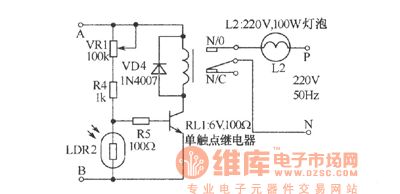
In the figure is a receiver that can avoid leaving out the sound of asking for help, in the daytime, only the receiver works and the lights automatically cut off. At night, the receiver and the lights can be sent out with the request of the patients. When the calling key is pressed, the primary stage of transformer X1 is also connected with the AC power supply at the same time, and after being rectified and filtered, the power supply of the second stage outputs a DC voltage which is delivered to the collecting electrode of VT1 by R1. If it is the daytime, due to the rays, LDR1 is in a low resistance, VT1 is conducting, and the collecting electrode is reduced to the earth connection.
(View)
View full Circuit Diagram | Comments | Reading(844)
| Pages:19/27 1234567891011121314151617181920Under 20 |
Circuit Categories
power supply circuit
Amplifier Circuit
Basic Circuit
LED and Light Circuit
Sensor Circuit
Signal Processing
Electrical Equipment Circuit
Control Circuit
Remote Control Circuit
A/D-D/A Converter Circuit
Audio Circuit
Measuring and Test Circuit
Communication Circuit
Computer-Related Circuit
555 Circuit
Automotive Circuit
Repairing Circuit
