Index 274
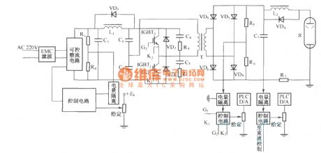
Main schematic circuit diagram of high-voltage power supply
Published:2011/3/24 21:26:00 Author:muriel | Keyword: Main schematic circuit diagram , high-voltage power supply
View full Circuit Diagram | Comments | Reading(722)
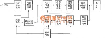
System chart of high-voltage power supply
Published:2011/3/24 21:29:00 Author:muriel | Keyword: System chart, high-voltage power supply
View full Circuit Diagram | Comments | Reading(513)
Samsung SAMSANG5508/7508 type color display switching power supply (DPl04P) circuit diagram
Published:2011/3/29 21:03:00 Author:Rebekka | Keyword: color display switching

Here is the schematic diagram of the Samsung SAMSANG5508/7508 type color display switching power supply (DPl04P)circuit:
(View)
View full Circuit Diagram | Comments | Reading(2232)
SHARP K-160170 type display circuit diagram
Published:2011/3/29 21:01:00 Author:Rebekka | Keyword: Display circuit

Here is the schematic diagram of the SHARP K-160170 type display circuit:
(View)
View full Circuit Diagram | Comments | Reading(743)
Panasonic TC-43P18G rear projection TV power supply circuit diagram
Published:2011/3/29 21:00:00 Author:Rebekka | Keyword: Panasonic, rear projection TV

Here is the schematic diagram of the Panasonic TC-43P18G rear projection TV power supply circuit: (View)
View full Circuit Diagram | Comments | Reading(5858)
Changhong HP5188 rear projection TV power supply circuit diagram
Published:2011/3/29 20:57:00 Author:Rebekka | Keyword: Changhong HP5188, rear projection TV

Here is the schematic diagram of the Changhong HP5188 rear projection TV power supplycircuit:
(View)
View full Circuit Diagram | Comments | Reading(3900)
Buck chopped wave switching power supply circuit diagram
Published:2011/3/24 21:42:00 Author:Nicole | Keyword: switching power supply

This is a buck chopped wave switching power supply circuit diagram. When the switching element VT is controlled as saturated conduction, the energy is stored in inductor L and capacitor C, and also is fed to the load. When the switching element VT is controlled as cut-off state, the energy stored in inductor and capacitor continue to supply the load, the diode VD constitute a current loop. Because of the switching element VT in series with the load resistor RL, so it is called series switching power supply.
Chopped wave switching power supply is a DC power supply, can obtain unidirectional square wave from switch circuit, and then can get a different steady DC which is different from the input voltage after filtered. The buck is whether the input voltage Ui is positive or negative, the output voltage Uo is always lower than the input voltage Ui, that is | Uo | ≤ | Ui |.
If the adjustment switching element VT has been conducting, the off-time is zero, then Uo = Ui; if VT has been cut-off, on-time is zero, then Uo = 0V. As the ratio of ton and toff is different, the output voltage Uo is between O ~ Ui.
(View)
View full Circuit Diagram | Comments | Reading(841)
Polarized absorption circuit-RLD network
Published:2011/3/21 1:26:00 Author: | Keyword: RLD network
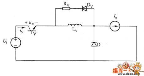
We can see from the table, relatively with parallel RCD network is series RLD network, this network is a polar opening absorption circuit. The components of RLD network are: Lv inductor and an Rv-Dv series branch parallel as shown.
absorber circuit
nonpolarity absorber circuit
heteropolarity absorber circuit
turn off absorb
Parallel Cv, du v/dt=Io/Cv
Parallel RCD(Rv, Dv Parallel, and serial with Cv)
open up absorb
serial Lv, di v/dt=Ui/Lv
serial RLD(Rv, Dv in serial, and Parallel with Lv)
The role of Rv-Dv series branch is in the process of shut off the switching tube, the electric energy stored in Lv can be released through the Rv-Dv series slip, avoided the switching tube was damaged due to the high voltage.
(View)
View full Circuit Diagram | Comments | Reading(546)
LTC732 pins arrangement diagram
Published:2011/4/6 2:38:00 Author:Nicole | Keyword: pin arrangement
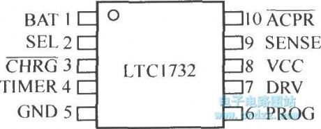
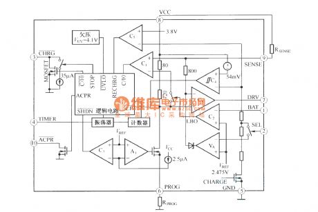
LTC732 is a lithium ion battery constant current/ constant voltage linear charge controller, it is produced by Linear Technology company. It also can constant current charge to nicad and Ni-MH battery, the pins arrangement diagram is shown as below:
The internal structure is shown as below:
(View)
View full Circuit Diagram | Comments | Reading(632)
Computer serial interface state indication circuit
Published:2011/4/6 1:10:00 Author:Nicole | Keyword: Computer, serial interface
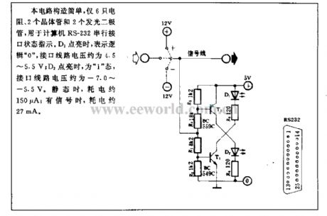
This circuit is simple in structure, only has 6 resistances, 2 transistor and 2 LED, it is used to the computer RS-232 serial interface state indication, when D1 lights up, it means logic 0 , the interface circuit voltage is about 4.5~5.5V; when D2 lights up, then in the 1 state, the interface circuit voltage is about -7.0~-5.5V. When it is static, the power consumption is about 150μA; when there is a singal, the power consumption is about 27mA. (View)
View full Circuit Diagram | Comments | Reading(554)
Computer photoelectric isolation interface circuit
Published:2011/4/6 1:23:00 Author:Nicole | Keyword: computer, photoelectric isolation, interface
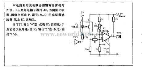
This circuit uses optocoupler to isolate the computer and peripheral device. IC2 is CCD; IC1 is threshold comparator, threshold voltage is adjusted by P1; R2, C2 form low-pass filter, to prevent IC1 from false triggering.
When TTL output is in the 0 state, to light up the primary of IC2, then its secondary turn-on, made IC1 output is in the 1 state, conversely, output is in the 0 state. (View)
View full Circuit Diagram | Comments | Reading(520)
Multipurpose exposure timing circuit
Published:2011/4/6 1:46:00 Author:Nicole | Keyword: multipurpose, exposure, timing

This device can satisfy photographic fans to master proper exposure, to ensure the quality of photos. It has the functions of high precision timing, wide common use, exposure timing, dimming, voltage regulation and so on. Amplifier bulb or electric iron, heating blanket, lamp, electric fan, motor and electrical equipments can connect to the output socket CZ, the output power is limited by controlled slicon capacity, if it is pure resistance load, then it can provide 600W power; if it is capacitive or inductive load, the output power is lower than 300W. (View)
View full Circuit Diagram | Comments | Reading(527)
5A regulated power supply(supply for TTL integrated circuit)composed of LM340T integrated regulator
Published:2011/4/6 0:42:00 Author:Nicole | Keyword: regulated power supply, integrated regulator
View full Circuit Diagram | Comments | Reading(595)
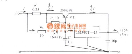
15V、5A regulated power supply composed of LM340T-15
Published:2011/4/6 0:44:00 Author:Nicole | Keyword: regulated power supply
View full Circuit Diagram | Comments | Reading(1073)
3A regulated power supply circuit composed of LM5000 integrated regulator(charging to TTL integrated circuit)
Published:2011/4/6 2:28:00 Author:Nicole | Keyword: 3A regulated power supply, integrated regulator
View full Circuit Diagram | Comments | Reading(511)
12V、5A regulated power supply composed of LM340K
Published:2011/4/6 0:44:00 Author:Nicole | Keyword: regulated power supply
View full Circuit Diagram | Comments | Reading(941)
15V、1A symmetry regulated power supply composed of LM340K-15
Published:2011/4/6 0:46:00 Author:Nicole | Keyword: regulated power supply, symmetry
View full Circuit Diagram | Comments | Reading(988)
12V、10A regulated power supply composed of LM340K-12
Published:2011/4/6 0:47:00 Author:Nicole | Keyword: regulated power supply
View full Circuit Diagram | Comments | Reading(1743)
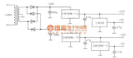
±5V and ±l2V regulated power supply composed of LM340K-12, LM309, LM320-5
Published:2011/4/6 0:51:00 Author:Nicole | Keyword: ±5V regulated power supply, ±l2V regulated power supply
View full Circuit Diagram | Comments | Reading(1149)
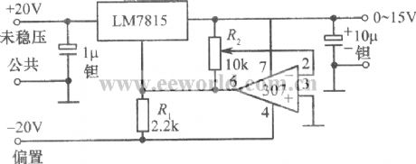
0~15V adjustable regulated power supply composed of LM7815, OPamp 307
Published:2011/4/6 2:26:00 Author:Nicole | Keyword: regulated power supply
View full Circuit Diagram | Comments | Reading(2791)
| Pages:274/291 At 20261262263264265266267268269270271272273274275276277278279280Under 20 |
Circuit Categories
power supply circuit
Amplifier Circuit
Basic Circuit
LED and Light Circuit
Sensor Circuit
Signal Processing
Electrical Equipment Circuit
Control Circuit
Remote Control Circuit
A/D-D/A Converter Circuit
Audio Circuit
Measuring and Test Circuit
Communication Circuit
Computer-Related Circuit
555 Circuit
Automotive Circuit
Repairing Circuit
