
Power-Supply Circuits-DC to DC
Index
DC to DC Converter 12 Volt to 21 Volt
Published:2013/3/22 3:55:00 Author:Ecco | Keyword: DC to DC Converter, 12 Volt to 21 Volt
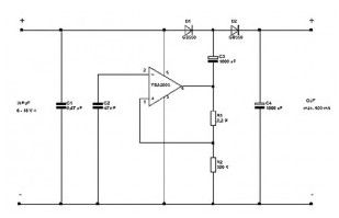
This 12 V to 21 V DC to DC Converter can perform nicely at 500mA maximum current. In case the current exceeds 500 milli-amperes, the voltage will drop below 21 Volt.
(View)
View full Circuit Diagram | Comments | Reading(1984)
Regulator DC-DC Circuit and Pin of Power Supply Monitor and its Main Features-MAX640/MAX653
Published:2011/9/13 23:45:00 Author:Zoey | Keyword: Regulator, DC-DC converter, Power Supply Monitor
Input voltage range of MAX640/MAX653 DC-DC converter is 4V~11.5V. Output voltage of MAX639 is 5.0V, MAX640 is 3.3V and MAX653 is 3.0V. For the converter, output current can reach 225mA, static working current is 10µA.
(View)
View full Circuit Diagram | Comments | Reading(633)
Regulator DC-DC Circuit and Pin of Power Supply Monitor and its Main Features-MAX1743
Published:2011/9/13 23:45:00 Author:Zoey | Keyword: Regulator, DC-DC Circuit, Pin of Power Supply Monitor, Converter

MAX1743 DC-DC converter can convert the voltage from +5V to±12V or to±15V. Connecting pin 4 to +V, andif the output current is 125mA, this converter will output ±12-V voltage; and connecting Pin 4 to the ground, the voltage output will be ±15V, and output current will be 100mA. Its output voltage range is±4%, efficiency 82%, reference voltage output 2.0V, working temperature range 0~70℃. This converter has circuits for periodic current detection, soft-start and low-voltage lock. (View)
View full Circuit Diagram | Comments | Reading(852)
Regulator DC-DC Circuit and Pin of Power Supply Monitor and its Main Features-REF-01 Reference Voltage Circuit(+10)
Published:2011/9/13 1:46:00 Author:Zoey | Keyword: Regulator, DC-DC Circuit, Pin of Power Supply Monitor, Reference Voltage Circuit

REF-01 reference voltage circuit (+10V) has thefeatures such as high accuracy, low temperature drift and low noise. Its output voltage is 10V, output voltage error ±0.3%, output voltage adjustment range±3%, temperature drift 3×10⁻⁶/℃, output current 20mA, output voltage range 8~33v.Working temperature of REF-01 and REF-01A is -55~+125℃, and REF-01E, REF-01H and REF-01C is 0~+70℃. The circuit has an interior protection circuit. (View)
View full Circuit Diagram | Comments | Reading(802)
Regulator DC-DC Circuit and Pin of Power Supply Monitor and its Main Features-REF-02 Reference Voltage Circuit(+5)
Published:2011/9/13 1:44:00 Author:Zoey | Keyword: Regulator, DC-DC Circuit, Pin of Power Supply Monitor, Reference Voltage Circuit

REF-02 reference voltage circuit (+5V) has thefeatures such as high accuracy, low temperature drift and low noise. Its output voltage is 5V, output voltage error ±0.3%, output voltage adjustment range±6%, temperature drift 3×10⁻⁶/℃, output current 20mA, output voltage range 8~33v.Working temperature of REF-02A is -55~+125℃, and REF-02E, REF-02C and REF-02D is 0~+70℃. The circuit has an interior protection circuit. (View)
View full Circuit Diagram | Comments | Reading(817)
Regulator DC-DC Circuit and Pin of Power Supply Monitor and its Main Features-Reference Voltage Circuit(+5)
Published:2011/9/13 1:42:00 Author:Zoey | Keyword: Regulator, DC-DC Circuit, Pin of Power Supply Monitor, Reference Voltage Circuit

REF-05 reference voltage circuit (+5V) has thefeatures such as high accuracy, low temperature drift and low noise. Its output voltage is 5V, output voltage error ±0.3%, output voltage adjustment range±6%, temperature drift 3×10⁻⁶/℃, output current 22mA, output voltage range 8~33v, maximum input voltage 40V and working temperature -55~+125℃. If the temperature drops to below 80℃, the power will be 500mW. The circuit has an interior short-circuit-proof circuit. (View)
View full Circuit Diagram | Comments | Reading(731)
Regulator DC-DC Circuit and Pin of Power Supply Monitor and its Main Features REF-10 Reference Voltage Circuit
Published:2011/9/13 0:17:00 Author:Zoey | Keyword: Regulator, DC-DC Circuit, Pin of Power Supply Monitor, Reference Voltage Circuit

REF-10 reference voltage circuit (+10V) has thefeatures such as high accuracy, low temperature drift and low noise. Its output voltage is +10V, output voltage error ±0.3%, output voltage adjustment range±0.3%, temperature drift 3×10⁻⁶/℃, long-term stability 50×10-6/1000hour, output current 20mA, output voltage range 13~33v, maximum input voltage 40V and working temperature -55~+125℃. If the temperature drops to below 80℃, the power will be 500mW. The circuit itself has an interior short-circuit-proof circuit. (View)
View full Circuit Diagram | Comments | Reading(624)
Regulator DC-DC Circuit and Pin of Power Supply Monitor and its Main Features SH1605A 5A Switched Regulator
Published:2011/9/13 0:13:00 Author:Zoey | Keyword: Regulator, DC-DC Circuit, Pin of Power Supply Monitor, Switched Regulator

The output current of SH1605A 5A switched regulators is 5A, and their output voltage ranges from 3.0V to 3.5V, the working frequency can be adjusted to 150kHz. The maximum voltage input is 40V, with the power of 20W. Working temperature of SH1605ASC is 0~+70℃, and SH1605ASM -55~+125℃. These regulators have interior frequency compensation and have high-speed soft free steering diodes, whose maximum positive current is 8.0A. 1Empty, 2 VREF, 3 Error Amplied Input ,4 CT, 5 Input, 6Empty, 7 Steering Diodes(Positive), 8 Output, frame ground.
(View)
View full Circuit Diagram | Comments | Reading(673)
Regulator DC-DC Circuit and Pin of Power Supply Monitor and its Main Features-MAX641/642/643
Published:2011/9/13 2:37:00 Author:Zoey | Keyword: Regulator, DC-DC Circuit, Boost Converter, COMS

MAX641/642/643 CMOS DC-DC boost converter is a switched inverted regulator, it has a interior MOS FET that has a peak of 325mA, this FET can constitute an inverted DC-DC converter with a fixed 10-W output. Therein, MAX 641 is 5V, MAX642 is 12V and MAX643 is 15V.For this converter, typical efficiency is 80% and outupt voltage error can be 5% or 10% and typical static current is 135µA. When the input voltage reaches 5V,oscillation frequency will be 45kHz and range of input voltage +2.0V~+16.5V. Maximum voltage of VOUT, LX and LBO terminal is 18V. Peak of output current of LX terminal is 325mA, LBO 50mA. If room temperature drops to below 50℃, power of DIP platic encapsulation will be 625mW, micro platic encapsulation will be 450mA, and ceramic encapsulation 800mW. Working temperature range of MAX641C/632C/643C is 0~+70℃, MAX641E/642E/643E -40~+85℃, MAX641M/642M/643M -55~+125℃. This converter has an interior circuit for low input voltage-detection
(View)
View full Circuit Diagram | Comments | Reading(732)
Regulator DC-DC Circuit and MAX663 CMOS Regulator
Published:2011/9/13 2:35:00 Author:Zoey | Keyword: Regulator, DC-DC Circuit,
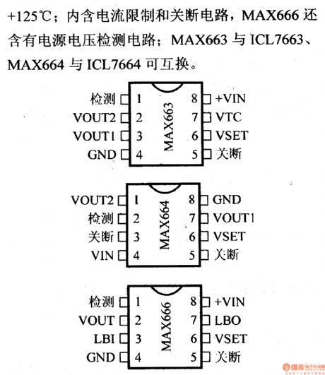
MAX663/666 refers to CMOS positive output regulator, while MAX664 refers to the negative one. If VSET is connected to the ground, output voltage of MAX663/666 will be 5V, and MAX666 will be -5V. If VSET is connected to external resistance, output voltage range of MAX663/666 will be 1.3~16V, and MAX664 will be -1.3~-16V. The output current is 40mA, static current is 12µA. Input voltage range of MAX663/666 is 2~16.5V, MAX664 is -2~-16.5V. Working temperature range of MAX663C/664C/666C is 0~+70℃, MAX663E/664E/666E -40~+85℃, MAX663M/664M/666M -55~+125℃. This regulator has circuits for current-restriction and power-off. MAX666 has a detection circuit for voltage of power supply. (View)
View full Circuit Diagram | Comments | Reading(812)
Regulator DC-DC Circuit and Pin of Power Supply Monitor and its Main Features-MAX631
Published:2011/9/13 2:59:00 Author:Zoey | Keyword: Regulator, DC-DC Circuit, CMOS, Boost Converter
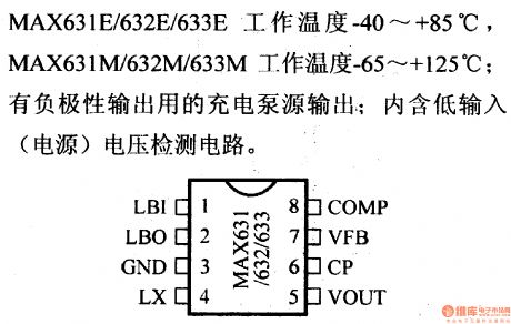
MAX631/632/633 CMOS DC-DC boost converter is a switched regulator, it has a interior MOS FET that has a peak of 325mA, this FET can constitute a DC-DC converter with a fixed output. Therein, MAX 631 5V, MAX632 12Vand MAX633 15V.For this converter, typical efficiency is 80%, typical working current 135µA, output voltage error 5% and 10%, oscillation frequency 45kHz. Maximum voltage of VOUT, LX and LBO terminal is 18V, peak of output current of LX is 325mA, LBO 50mA. If room temperature drops to below 50℃, power of DIP platic encapsulation will be 625mW, micro platic encapsulation will be 450mA, and ceramic encapsulation 800mW. Working temperature range of MAX631C/632C/633C is 0~+70℃, MAX631E/632E/633E -40~+85℃, MAX631M/632M/633M -65~+125℃. This converter has an interior circuit for low input voltage-detection and an output pump for spare negative ouput.
(View)
View full Circuit Diagram | Comments | Reading(769)
Regulator DC-DC Circuit and Pin of Power Supply Monitor and its Main Features- MAX635/636/637
Published:2011/9/13 2:54:00 Author:Zoey | Keyword: Regulator, DC-DC Circuit, COMS, Boost Converter, Inverted Output
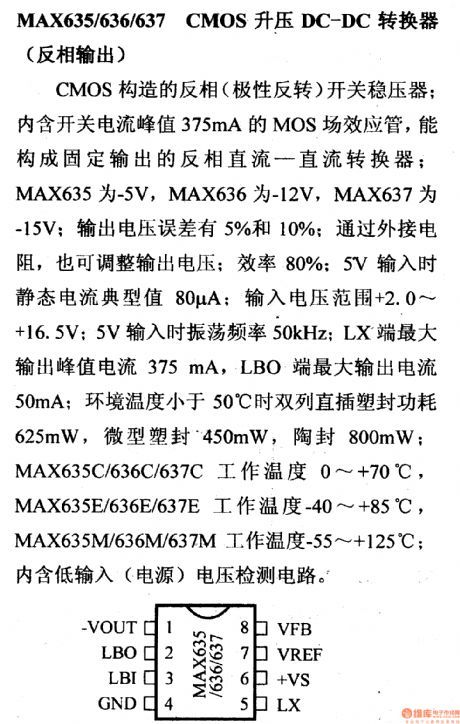
MAX635/636/637 CMOS DC-DC boost converter is a switched inverted regulator, it has a interior MOS FET that has a peak of 375mA, this FET can constitute an inverted DC-DC converter with a fixed output. Therein, MAX 635 -5V, MAX636 -12V and MAX633 -15V.For this converter, typical efficiency is 80%. When the input voltage reaches 5V, typical static current will be 85µA, oscillation frequency 45kHz and range of input voltage +2.0V~+16.5V. Peak of output current of LX terminal is 325mA, LBO 50mA. If room temperature drops to below 50℃, power of DIP platic encapsulation will be 625mW, micro platic encapsulation will be 450mA, and ceramic encapsulation 800mW. Working temperature range of MAX635C/636C/637C is 0~+70℃, MAX635E/636E/637E -40~+85℃, MAX635M/636M/637M -55~+125℃. This converter has an interior circuit for low input voltage-detection
(View)
View full Circuit Diagram | Comments | Reading(707)
RegulatorDC-DC Circuit and Pin of Power Supply Monitor and its Main Features
Published:2011/9/13 0:22:00 Author:Zoey | Keyword: Regulator, DC-DC Circuit, Pin of Power Supply Monitor, Main Features
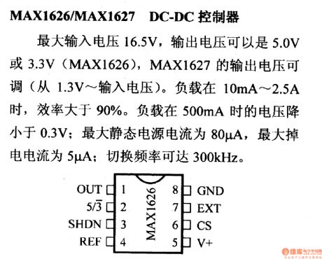
The maximum input voltage of MAX1626/MAX1627 DC-DC controller is 16.5V, output voltage of MAX1626 can be 5.0V or 3.3V,while output voltage of MAX1627 can be adjusted from 1.3V to itsinput voltage. If the load is between 10mA to 2.5A, efficiency will exceed 90%. Voltage will descend to below 0.3V when the load ranges from 10mA to 2.5A. The maximum static current of the power supply is 80µA, the maximum power-off current is 5µA. The Switched frequency can be as large as 300kHz. (View)
View full Circuit Diagram | Comments | Reading(828)
Circuit diagram of DC converter from 12V to 24 V
Published:2011/9/7 0:54:00 Author:Vicky | Keyword: DC converter

Different types of voltage value such as 15V, 16V, 18V, 20V, 22V, and 24V etc. can be changed by changing the resistance.
L1 uses a magnetic loop of 2cm and 1.7 polyester varnished wires to wind it closely for 35 turns. And then it is sealed up by silicon rubber, otherwise it is easy to generate sizzling sound.
Meanwhile the direction of the route should be paid attention to, otherwise the sizzling sound will also occurand the field-effect tube emits heat and destroys due to the self-excitation caused by routing problem. If possible, paster component of UC3843 can also be used.
L2 can use the magnetic loop of old energy-saving light to wind closely. There is no special requirement.
(View)
View full Circuit Diagram | Comments | Reading(7054)
ZCS PWM DC/DC converter circuit diagram
Published:2011/9/7 4:08:00 Author:Vicky | Keyword: ZCS PWM DC/DC converter


Topological structure: Buck DC/DC ZCS PWM converter, main switch T1 (including antiparallel diode D1), booster diode T2 (D2 is the antiparallel diode of T2).
Suppose thatthe diode switches are all ideal devices; the inductances and capacitances are all ideal components; Cr is big enough, Lf is also big enough, and Lf>>Lr. I switching cycle, output voltage is 0, remaining and unchanged; if it retains Io, unchanged, so Lf, Cf and load resistance can be regarded as a constant current source Io.
The state of switch: In a switching cycle Ts, converter has 5 switching state. Every switching state has a corresponding equivalence circuit. (View)
View full Circuit Diagram | Comments | Reading(2912)
Regulator DC-DC Circuit and Pin of Power Supply Monitor and its Main Features TA7501S Amplified Circuit
Published:2011/9/6 2:57:00 Author:Zoey | Keyword: Regulator, DC-DC Circuit, Pin of Power Supply Monitor, Amplified Circuit

TA7501S Amplified Circuit controlled by Leakage Current
The circuit that can be cut off by high-speed leakage current is available for leakage cutters,which have a sensitivity of 15mA. The typical value of trip voltage is 7mV and it will turn to be 1ms when it increases. The maximum current of the power supply is 10mA and the power is 400mW. The working temperature is between -40 ℃to +85℃. The lock circuit itself has an interior voltage stabilizing circuit and an interior SCR rectifier that can conduct externally. (View)
View full Circuit Diagram | Comments | Reading(687)
Regulator DC-DC Circuit and Pin of Power Supply Monitor and its Main Features TA7179P Tracking Regulator
Published:2011/9/6 2:57:00 Author:Zoey | Keyword: Regulator, DC-DC Circuit, Pin of Power Supply Monitor, Main Features, Positive output

TA7179P tracking regulator can output±15V voltage, and this value can be turned to be±8V by using VADJ terminal and external resistance. The current output is 100mA and the temperature drift is 0.007%/℃,the maximum voltage output is ±30V. (View)
View full Circuit Diagram | Comments | Reading(1954)
Regulator DC-DC Circuit and Pin of Power Supply Monitor and its Main Features TA7089P Compressible Regulator(Positive Output)
Published:2011/9/6 3:00:00 Author:Zoey | Keyword: Regulator, DC-DC Circuit, Pin of Power Supply Monitor, Compressible Regulator(Positive Output)

TA8909 adjustable regulator(Positive output) can output adjustable voltage, which ranges from 3.3V to 33V. The maximum current output is 200mA and the typical value of impedance output is 40Ω. The maximum voltage input is 35V, with the power of 600mW. The working temperature is between -30℃ to +75℃. (View)
View full Circuit Diagram | Comments | Reading(1087)
Regulator DC-DC Circuit and Pin of Power Supply Monitor and its Main Features SI-3000C Regulator
Published:2011/9/6 2:58:00 Author:Zoey | Keyword: Regulator, DC-DC Circuit, Pin of Power Supply Monitor, Positive Output

SI-3000C series regulators(positive output ) are five-terminal regulators that have low voltage margins. The voltage output can be 5V, 9V, 12V, 15V and 24V. The outout voltage can also be adjusted by the resistance between remote sensing terminal and output terminal. The output current is 1.5A and the output voltage margin can decrease to less than 0.5V when the current turns to be 1A. Maximum output voltage of SI-3050C and SI-3090C is 35V, SI-3120C and SI-3150C 40V, SI-3240C 45V. The working temperature is between -30℃to +100℃.Each of themhas an interior overcurrent, overvoltage and overtemperature-proof circuit. (View)
View full Circuit Diagram | Comments | Reading(836)
Regulator DC-DC Circuit and Pin of Power Supply Monitor and its Main Features Tracking regulator
Published:2011/9/6 3:25:00 Author:Zoey | Keyword: Regulator, DC-DC Circuit, Pin of Power Supply Monitor, Tracking regulator

Interior output voltage of NJM 2353 tracking regulators is ±15V, and output voltage can be adjusted to 10~23V by the voltage adjusting terminal of the tracking regulator. The output current is ±100mA, maximum output voltage±30V, the power 700mW and the working temperature -20~+75℃. This regulator has an interior current-limiting circuit. (View)
View full Circuit Diagram | Comments | Reading(692)
| Pages:1/2 12 |
Circuit Categories
power supply circuit
Amplifier Circuit
Basic Circuit
LED and Light Circuit
Sensor Circuit
Signal Processing
Electrical Equipment Circuit
Control Circuit
Remote Control Circuit
A/D-D/A Converter Circuit
Audio Circuit
Measuring and Test Circuit
Communication Circuit
Computer-Related Circuit
555 Circuit
Automotive Circuit
Repairing Circuit