Power-Supply Circuits-DC to DC
ZCS PWM DC/DC converter circuit diagram
Published:2011/9/7 4:08:00 Author:Vicky | Keyword: ZCS PWM DC/DC converter | From:SeekIC
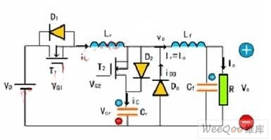
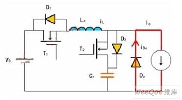
Topological structure: Buck DC/DC ZCS PWM converter, main switch T1 (including antiparallel diode D1), booster diode T2 (D2 is the antiparallel diode of T2).
Suppose thatthe diode switches are all ideal devices; the inductances and capacitances are all ideal components; Cr is big enough, Lf is also big enough, and Lf>>Lr. I switching cycle, output voltage is 0, remaining and unchanged; if it retains Io, unchanged, so Lf, Cf and load resistance can be regarded as a constant current source Io.
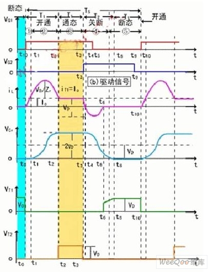
The state of switch: In a switching cycle Ts, converter has 5 switching state. Every switching state has a corresponding equivalence circuit.
Reprinted Url Of This Article:
http://www.seekic.com/circuit_diagram/Power_Supply_Circuit/Power-Supply_Circuits-DC_to_DC/ZCS_PWM_DC_DC_converter_circuit_diagram.html
Print this Page | Comments | Reading(3)

Article Categories
power supply circuit
Amplifier Circuit
Basic Circuit
LED and Light Circuit
Sensor Circuit
Signal Processing
Electrical Equipment Circuit
Control Circuit
Remote Control Circuit
A/D-D/A Converter Circuit
Audio Circuit
Measuring and Test Circuit
Communication Circuit
Computer-Related Circuit
555 Circuit
Automotive Circuit
Repairing Circuit
Code: