
Electrical Equipment Circuit
Index 124
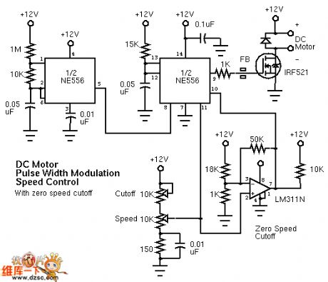
DC electric machine PWM speed circuit principle circuit
Published:2011/3/28 22:25:00 Author:may | Keyword: DC electric machine PWM speed circuit
View full Circuit Diagram | Comments | Reading(732)
Electric fan tapped reactor speed circuit
Published:2011/3/28 22:27:00 Author:may | Keyword: Electric fan tapped reactor speed

Electric fan tapped reactor speed circuit is shown in the diagram:
(View)
View full Circuit Diagram | Comments | Reading(458)
Buick wiper and washer circuit
Published:2011/3/30 1:20:00 Author:Jessie | Keyword: wiper, washer

View full Circuit Diagram | Comments | Reading(755)
MOTOROLA V2288 mobile phone rf circuit
Published:2011/3/30 22:49:00 Author:Jessie | Keyword: mobile phone rf

View full Circuit Diagram | Comments | Reading(938)
Electronic absorb dome light circuit and maintenance circuit
Published:2011/3/30 21:22:00 Author:Jessie | Keyword: absorb dome light, maintenance
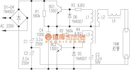
AC 220V rectified by the D1 ~ D4, C1, C2 filtering. C1 and C2 are series, can directly supply powertotubes to save charging capacitance, also reduced the compression requirements. R1 is startup resistance, provides BG2 forneeded initial voltage, R2 is bias resistors, BG1, BG2 and L1, L2, L3 compose theoscillating circuit, diodeD5 provides dischargecircuit for C3. L1 and L3 respectively connected to the bases of BG1 and BG2, which makes BG1 and BG2 get positive feedback voltageto initial. So that BG1 and BG2 turn in connected. High-frequency voltage formed in tubeto lighten it.
(View)
View full Circuit Diagram | Comments | Reading(703)
TV LED electronic forceps monitoring circuit diagram
Published:2011/3/30 21:19:00 Author:Ecco | Keyword: TV, LED electronic forceps

When the switch places(2), the output voltage is homology to input voltage, if the voltage were normal(200~240 V),both of two luminotrons couldn't be bright. When the voltage rises to 250 V, the rise of A electric potential will make red luminotron bright, when the switch places(2), then make output be 220V, the red luminotron again douses again. When Lou voltage drop arrived at 190 V, the green luminotron will be bright, the switch places(3).
(View)
View full Circuit Diagram | Comments | Reading(1292)
LED Holiday lights controller circuit diagram 6
Published:2011/3/30 20:37:00 Author:Ecco | Keyword: LED Holiday lights, controller

The LED holiday lights controller introduced in the example can display four sentences four words composing of many LEDs(such as celebrating May Day and long live our motherland ), and they display in time sequence to add festive atmosphere to festive night.
Circuit principle of work
This LED holiday lights controller circuit is composed of power supply circuit, pulse generator and control circuit and LED display circuit component, as shown in figure.
Power circuit is composed of voltage step-down capacitor Cl, bleeder resistors Rl, rectifier diode VDl, VD2, voltage-regulator diode VS and filter capacitor C2.
Pulse generator is composed of time-based integrated circuit ICl, resistor R2, R3 and capacitor C3, C4.
Control circuit is composed of decimal count/pulse splitter integrated circuit IC2, diodes VD3, resistors R4 - R8 and capacitor C5 and thyristor VTl-VW. (View)
View full Circuit Diagram | Comments | Reading(641)
The elementary diagram of electronic biological wave physical circuit
Published:2011/3/29 20:01:00 Author:Ecco | Keyword: electronic biological wave, physical circuit

The elementary diagram of electronic biological wave physical circuit is as below:
(View)
View full Circuit Diagram | Comments | Reading(1782)
Induction cooker schematic circuit diagram
Published:2011/3/23 1:40:00 Author:Ecco | Keyword: Induction cooker

View full Circuit Diagram | Comments | Reading(6696)
Telephone Schematic
Published:2011/3/21 1:28:00 Author:Joan | Keyword: Telephone

The figure is Telephone Schematic. (View)
View full Circuit Diagram | Comments | Reading(3935)
KangBao C12C - 15B induction cooker power driving output stage circuit diagram
Published:2011/3/29 1:57:00 Author:Ecco | Keyword: induction cooker , power driving output stage

KangBao C12C - 15B induction cooker power driving output stage circuit diagram is as below:
(View)
View full Circuit Diagram | Comments | Reading(2555)
Electric blanket automatic protection constant temperature circuit
Published:2011/3/21 1:33:00 Author:Allen | Keyword: Electric blanket, automatic protection, constant temperature


Currently, many electric blankets temperature control use manually switch, which adopts a fast and a slow thermal step for temperature control, so that the internal temperature of electric blanket is difficult to control at a constant temperature to work, as a result, a lot of trouble is brought. This paper introduces a electric blanket automatic control circuit, which can not only work at a predetermined temperature, but also play a role in self-locking power and over voltage protection.
The circuit principle is shown in figure 1. It consists of power-failing and self-locking circuit, overvoltage protection and automatic constant temperature control circuit. When the button switch S2 is pressed, 220V AC is used for relay J after passing capacitor C2 step-down voltage, V6 and V7 regulator rectifier and C3 filter, then J powered on and normally open contact J1 connected make the circuit self-locking. At this time, it can maintain power to the electric blanket and the relay J, even if the button switch S2 releases. When encountered power outage in the use of electric blanket, the relay J powers off and release, normally open contact J1 powers off, so the electric blanket does not work. When the power grid restores power supply, the relay and electric blankets can not automatically power on, only press s2 again, and the relay J pull, so electric blankets will be re-energized work.
Rt is a positive temperature coefficient thermistor. Its internal resistance varies with the high and low temperature, that is, at high temperature, the internal resistance increases, and vice versa. The electric blankets constant temperature control circuit is composed of the rectifier diode V2 ~ V5, one-way thyristor SCR, two-way trigger diode V1, positive temperature coefficient thermistor Rt, capacitor C1, RP potentiometer. The control process is: AC turns into DC by V2 ~ V5 bridge rectifier, charge to C1 by RP and Rt, when the voltage of C1 reaches a certain value, the bi-directional trigger diode conducts and breakdowns in a discharge state. At this point, one-way thyristor SCR is triggered and powered on, which make the blanket work. When internal temperature in the electric blanket rises a certain value, the internal thermistor resistance Rt is great, but the voltage of C1 is small, which can not make V1 breakdown, so the SCR turn-off. Relatively, the electric blanket is off and does not work, it is in a cooling state. When the electric blanket temperature drops to a certain value, then repeat the control process, so keep the cycle, and make the blanket temperature at a constant value. If the grid appears over voltage, varistor MY internally (ie in-state) is short circuit, and quickly burn out fuse RD, and thus play a role in over-voltage automatic protection. Figure 2 is the device's printed circuit board assembly drawing.
(View)
View full Circuit Diagram | Comments | Reading(3805)
Warm blower circuit
Published:2011/3/21 1:27:00 Author:Allen | Keyword: Warm blower

View full Circuit Diagram | Comments | Reading(737)
LCD TV power supply circuit diagram
Published:2011/3/27 20:34:00 Author:Rebekka | Keyword: LCD TV

LCD TV power supply circuit diagram is shown as below.
(View)
View full Circuit Diagram | Comments | Reading(12908)
Tire pressure gauge circuit diagram
Published:2011/3/20 22:51:00 Author:Ecco | Keyword: Tire pressure gauge
Tire pressure gauge circuit diagram is as below:
(View)
View full Circuit Diagram | Comments | Reading(1275)
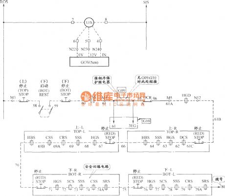
Mitsubishi automatic escalator safety loop circuit
Published:2011/3/22 22:38:00 Author:Jessie | Keyword: automatic, escalator, safety loop
View full Circuit Diagram | Comments | Reading(1149)
Mitsubishi escalator main circuit
Published:2011/3/22 22:36:00 Author:Jessie | Keyword: escalator

View full Circuit Diagram | Comments | Reading(2756)
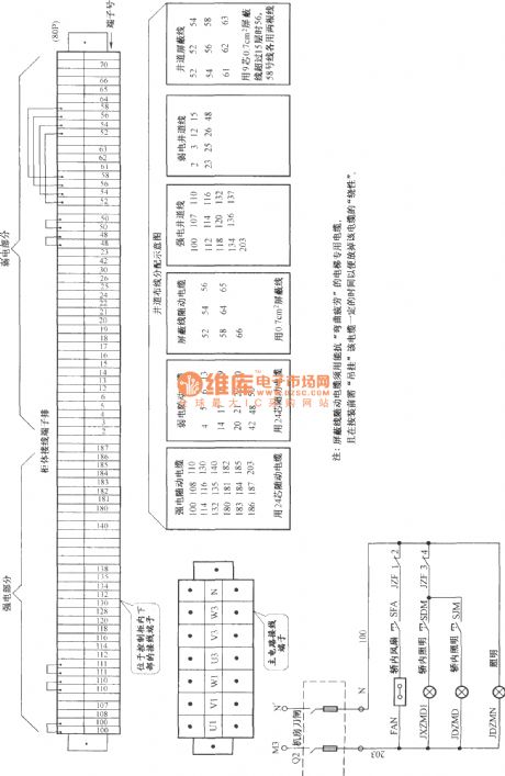
Tianjin zhengda elevator terminals arrangment diagram
Published:2011/3/22 22:35:00 Author:Jessie | Keyword: elevator, terminals arrangment
View full Circuit Diagram | Comments | Reading(519)
Tianjin zhengda elevator main circuit and safety circuit
Published:2011/3/22 22:35:00 Author:Jessie | Keyword: main circuit, safety circuit

View full Circuit Diagram | Comments | Reading(2503)
Xunda automatic escalator safety loop circuit
Published:2011/3/22 22:34:00 Author:Jessie | Keyword: automatic, escalator, loop circuit

View full Circuit Diagram | Comments | Reading(912)
| Pages:124/126 At 20121122123124125126 |
Circuit Categories
power supply circuit
Amplifier Circuit
Basic Circuit
LED and Light Circuit
Sensor Circuit
Signal Processing
Electrical Equipment Circuit
Control Circuit
Remote Control Circuit
A/D-D/A Converter Circuit
Audio Circuit
Measuring and Test Circuit
Communication Circuit
Computer-Related Circuit
555 Circuit
Automotive Circuit
Repairing Circuit