
Electrical Equipment Circuit
Index 122
engine oil pressure switch、water temperature sensor、braking smoke and air condition system circuit diagram
Published:2011/4/10 20:39:00 Author:muriel | Keyword: engine oil pressure switch, water temperature sensor, braking smoke , air condition system
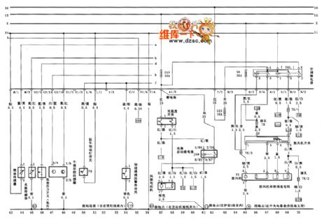
Figure engine oil pressure switch、water temperature sensor、braking smoke and air condition system circuit diagram (View)
View full Circuit Diagram | Comments | Reading(1740)
Air-condition front and back control assembly and ambient temperature control circuit diagram
Published:2011/4/10 20:25:00 Author:muriel | Keyword: Air-condition front and back control assembly, ambient temperature control
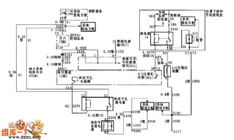
Figure Air-condition front and back control assembly and ambient temperature control circuit diagram (View)
View full Circuit Diagram | Comments | Reading(511)
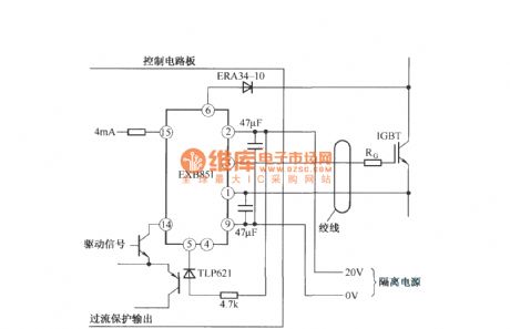
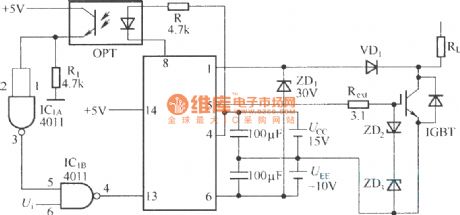
The application circuit of EXB851
Published:2011/4/8 2:26:00 Author:may
View full Circuit Diagram | Comments | Reading(656)
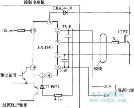
Application circuit of EXB840
Published:2011/4/8 2:10:00 Author:may
View full Circuit Diagram | Comments | Reading(1107)
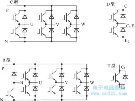
D type IPM structure and IGBT equivalent circuit
Published:2011/4/8 2:01:00 Author:may | Keyword: D type, IPM, structure, equivalent

(a) D type IPM structure (b) IGBT equivalent circuit (View)
View full Circuit Diagram | Comments | Reading(1074)
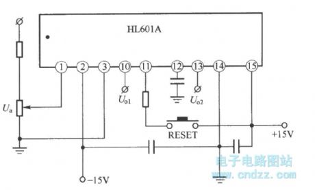
Typical application wiring diagram of HL610A
Published:2011/4/8 1:57:00 Author:may
View full Circuit Diagram | Comments | Reading(641)
Power module unit diagram of IGBT and fly-wheel diode
Published:2011/4/8 1:07:00 Author:may | Keyword: IGBT, fly-wheel diode, Power module
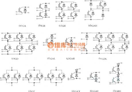
(a) is single switch module;
(b) is two unit (half bridge) module;
(c) is H bridge (single phase bridge) module;
(d) is asymmetrical H bridge module;
(e) is three phase bridge (six unit or inverter bridge) module;
(f) is chopping module
(g) is chopping module
(h) is three phase bridge GD add chopping GAL (braking chopper circuit) module;
(i) is three unit module, consists of three group switch;
(j) is single switch add collector end series diode ( negative direction disconnecting switch) module;
(k) is single switch add emitter end series diode (negative direction disconnecting switch) module;
(l) is two unit module, with series diode (negative direction disconnecting switch). (View)
View full Circuit Diagram | Comments | Reading(3449)
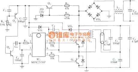
CFL electron ballast circuit composed of MPIC2151P and PowerLuxTM IGBT
Published:2011/4/2 3:25:00 Author:may | Keyword: electron ballast, PowerLuxTM IGBT
View full Circuit Diagram | Comments | Reading(1554)
The package of Mitsubishi IPM
Published:2011/4/7 20:48:00 Author:may | Keyword: Mitsubishi,
IPM is advanced hybrid integrated power device. It is integrated high-speed, low power consumption IGBT chip and optimal grid drive circuit and kinds of protective circuit in one module. Compare to ordinary IGBT, IPM has further increase in system features and reliability. Also, because its conduction losses and switch losses is quite low, the size of radiator is small, so size of the whole system is more small. Moreover IPM internal integrated logic, control, detect ion and protect circuit, the use is convenient, it not only decrease the volume of this system and the development time, also greatly add reliability of the system. (View)
View full Circuit Diagram | Comments | Reading(1140)
Zero-voltage zero-current switch three-level DC converter
Published:2011/4/7 20:34:00 Author:may | Keyword: zero-voltage zero-current switch, three-level DC converter


In order to remove circulating current of zero-voltage switch three-level DC converter in zero state, we come up with kind of zero-voltage zero-current switch three-level DC converter circuit. The circuit is shown in the following diagram
1, the main difference between this circuit and zero-voltage switch three-level DC converter is: add coupling capacitance C55 and add pilot switch SAUX and clamp capacitance CAUX in transformer secondary winding; coupling capacitance C55 separately connect the switch process of outer outer-side tube VT1, VT4 and in side tube VT2, VT3.
2, this circuit adopts blocking capacitor as blocking voltage source, let transformer once side current decrease to zero in zero state, thereby achieve zero current switch of in side switch tube.
3, This diagram separately series diode VT2 and VT3 in branch circuit of VT2 and VT3 in order to prevent the transformer once side current to continue flow in negative direction in zero state. It removes the minus effect after adding saturated inductance.
(View)
View full Circuit Diagram | Comments | Reading(2045)
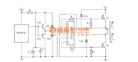
TX-KD201 driving two normal shock or two backlash circuit cording diagram
Published:2011/4/6 4:08:00 Author:may | Keyword: two normal shock, two backlash
View full Circuit Diagram | Comments | Reading(505)
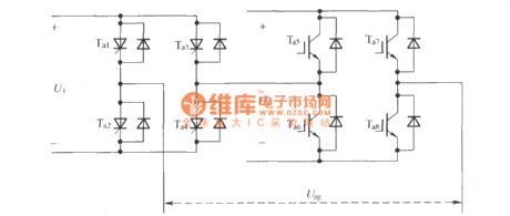
Asymmetric hybrid cascaded type multilevel converter single-phase topological structure
Published:2011/4/6 3:53:00 Author:may | Keyword: Asymmetric, hybrid cascaded type, multilevel converter, single-phase, topological structure
View full Circuit Diagram | Comments | Reading(520)
Soft switching PWM three-level convertor using transformer secondary additional winding
Published:2011/4/6 3:39:00 Author:may | Keyword: Soft switching PWM, three-level convertor, transformer secondary additional winding

View full Circuit Diagram | Comments | Reading(973)
M57962L typical application example
Published:2011/4/6 5:06:00 Author:may
View full Circuit Diagram | Comments | Reading(2556)
M57962AL application circuit
Published:2011/4/6 5:06:00 Author:may

View full Circuit Diagram | Comments | Reading(1022)
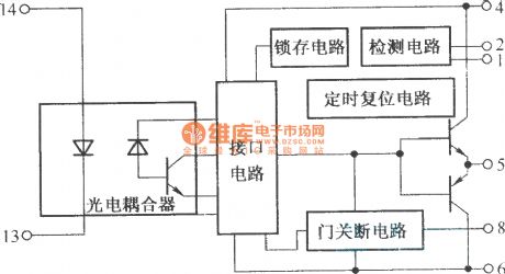
M57962AL internal structure block diagram
Published:2011/4/6 5:04:00 Author:may | Keyword: internal structure
View full Circuit Diagram | Comments | Reading(629)
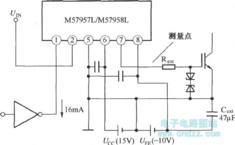
Typical application circuit of M57957L and M57958L
Published:2011/4/6 5:02:00 Author:may
View full Circuit Diagram | Comments | Reading(728)
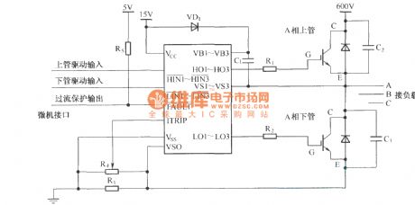
Attended mode of IR2130 and power valve
Published:2011/4/6 4:34:00 Author:may | Keyword: Attended mode, power valve
View full Circuit Diagram | Comments | Reading(2384)
The application of IR2110 in three phase bridge motor drive circuit
Published:2011/4/7 19:59:00 Author:may | Keyword: three phase bridge, motor drive

View full Circuit Diagram | Comments | Reading(7970)
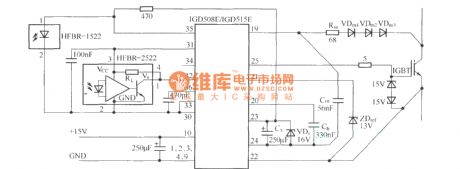
IGD508E/IGD515E application circuit
Published:2011/4/7 5:17:00 Author:may
View full Circuit Diagram | Comments | Reading(844)
| Pages:122/126 At 20121122123124125126 |
Circuit Categories
power supply circuit
Amplifier Circuit
Basic Circuit
LED and Light Circuit
Sensor Circuit
Signal Processing
Electrical Equipment Circuit
Control Circuit
Remote Control Circuit
A/D-D/A Converter Circuit
Audio Circuit
Measuring and Test Circuit
Communication Circuit
Computer-Related Circuit
555 Circuit
Automotive Circuit
Repairing Circuit