Medical
Index
The electronic pulse meter (CD4553, CD4511)
Published:2013/1/25 1:30:00 Author:Ecco | Keyword: electronic pulse meter
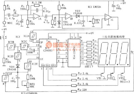
Pulse meter and heart rate meter is actually a kind of instrument with another name, and two instruments use different sampling sites. Heart rate meter usually samples from the chest, but the pulse analyzer general samples from the wrist. The following electronic pulse instrument is shown as figure.
(View)
View full Circuit Diagram | Comments | Reading(5233)
PVDF heart sound pulse measurement principle circuit
Published:2012/12/13 1:17:00 Author:Ecco | Keyword: PVDF , heart sound , pulse measurement
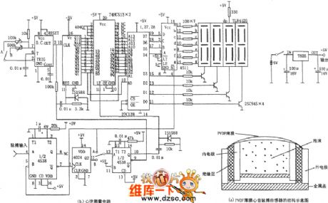
Measuring circuit is composed of monostable oscillator ( 4538 ), the divider ( 4024), pulse generator ( ICM7555 ), counter ( 4040), latch ( 74HC513 ), memory ( ROM ), seven-segment latch drive ( 7511 ) and seven-segment digital LED tube. Figure (a) is a structural diagram of the PVDF heart sound pulse sensor. In Figure ( a ), PVDF film is dome-shaped and slightly protruding outward to make a good contact with the skin surface. The PVDF material is flexible to close to the skin, the impedance is matching with the skin, subsequently, even under stress, the pressure does not affect the detection pulse pressure variation, and therefore able to detect a slight ripple signal.
(View)
View full Circuit Diagram | Comments | Reading(2087)
Sleep Aid in case of insomnia
Published:2012/9/18 21:18:00 Author:Ecco | Keyword: Sleep Aid, in case of, insomnia
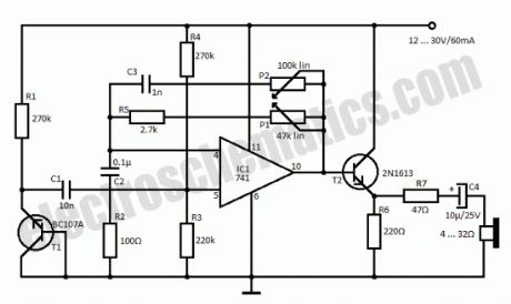
Insomnia treatment consist mostly of sleeping pills consumption but this circuit is an alternative for that and consists of a simple circuit that generates a rain sound effect. The japanese researches were the first to discover that sound of rain has a relaxing effect. With the help of this simple circuit we can generate the rain sound which can be a sleep aid in case of insomnia.T1 is used as a noise generator and its signal is amplified by the 741 IC and thru T2, R7 and C4 goes to a headset with low resistance. If you do not want to use the headphones then use a speaker with impedance between 4 and 16 Ω. With the help of P1 can adjust sound level and with P2 the tone.
Sleep Aid Circuit Schematic
?
5 Responses to “Sleep Aid in case of insomnia”
Source: electroschematics.com
(View)
View full Circuit Diagram | Comments | Reading(1893)
Heartbeat Sensor (Tranduscer)
Published:2012/9/3 2:00:00 Author:Ecco | Keyword: Heartbeat Sensor, Tranduscer
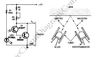
To build a heart-beat transducer not as difficult as imagined. Circuit below shows a simple heart-beat transducer.
This circuit made from an infrared phototransistor and infrared LED. This transducer works with the principle of light reflection,in this case the light is infrared. The skin is used as a reflective surface for infrared light. The density of blood in the skin will affect on the IR reflectivity. The pumping action of heart causes the blood density rises and falls. So that we can calculate the heart rate based on the rise and fall of intensity of infrared that reflected by skin.
Source: freecircuitdiagram
(View)
View full Circuit Diagram | Comments | Reading(2247)
Simple Lie Detector
Published:2012/9/3 1:58:00 Author:Ecco | Keyword: Simple , Lie Detector

Source: freecircuitdiagram
To know someone is lying or not we can use lie detector. This is a simple lie detector that can be made in minutes. It works to detect the someone who telling lie but it is not as sophisticated as the ones the professionals use. Here is the schematic diagram of this circuit:
The skin resistance will go down when someone telling lie and this circuit works by measuring it. We can use electrode pads, alligator clips, or just wires and tape as the electrodes. We have to adjust R2 to position the meter at the center at the beginning of the interrogation (relax condition), then we can know someone is lying when the meter changes in response to a question.
(View)
View full Circuit Diagram | Comments | Reading(0)
Single Cell 1.5V Hearing Aid
Published:2012/9/3 1:57:00 Author:Ecco | Keyword: Single Cell , 1.5V, Hearing Aid
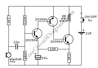
Source: freecircuitdiagram
This circuit can be assembled in a small board, or you can even do it without board. To assemble without board, you can connect every component leads each other and solder them. Align the component bodies and their leads to avoid shorts, secure with insulation tape, glue, or resin.
This is a hearing aid circuit with 1.5v supply. This circuit is used to detect very faint sounds, then deliver the sounds to an 8 ohm earpiece. This circuit requires 1.5v input voltage, need only a single cell battery. Here is the schematic diagram of the circuit:
(View)
View full Circuit Diagram | Comments | Reading(3872)
Electronic biological wave physiatrics instrument circuit
Published:2011/10/31 4:02:00 Author:May | Keyword: Electronic biological wave, physiatrics instrument

Electronic biological wave physical physiatrics instrument is shown in the following diagram, it can generate the compoundsignal with various frequency, and it canhelp patients absorb medications,and italso hasdirect effect on the human body acupuncture point for treatment.
(View)
View full Circuit Diagram | Comments | Reading(2270)
E-anesthetic circuit diagram
Published:2011/9/15 22:46:00 Author:Rebekka | Keyword: E-anesthetic

As shown is the electronic anesthesia circuit. The circuit can output 8 groups of electrode which output at the same time independently. Regulating any one of the groups, other groups will not be affected. You can choose the 2Hz ~ 50Hz frequency range. Generally taking 2 ~ 3Hz operating frequency will make 8-output cost 100mW power. Since the transistor oscillator is basically a constant current source, when 2 more groups output at the same time(such as 4 groups), if one group outputs high, the negative pulse output of other groups will be low. That means, they will influence each other. It is bad for E-anesthetic. So we should avoid this situation. To eliminate this shortcoming. We can add one Zener diode at both ends of the oscillator output transformer primary winding,. It play the role of limiting the regulator. (View)
View full Circuit Diagram | Comments | Reading(1646)
Amblyopia dual digital display therapeutic apparatus circuit diagram
Published:2011/9/14 21:10:00 Author:Rebekka | Keyword: Amblyopia , dual digital display, therapeutic apparatus
View full Circuit Diagram | Comments | Reading(1484)
Seashore biofeedback therapy device circuit diagram
Published:2011/9/8 21:00:00 Author:Lucas | Keyword: Seashore biofeedback, therapy device
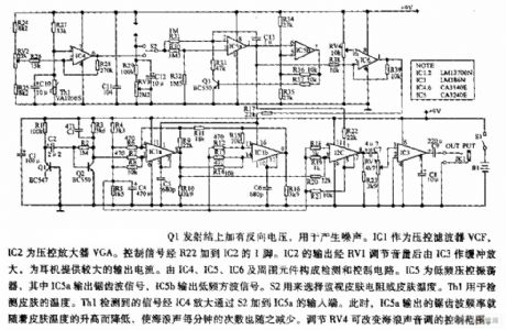
The Q1 emitter junction is added reverse voltage for generating noise. IC1 is used as a voltage-controlled filter VCF, and IC2 is the voltage-controlled amplifier VGA. Controlling signal is added to the pin 1 of IC2 by R22. IC1's output is adjusted by RV1, then buffered and amplified by IC3 to provide a larger output current for the headphones. The IC4, IC5, IC6 and the surrounding components form the detection and control circuit. IC5 is the low-frequency voltage-controlled oscillator, and IC5a outputs sawtooth signal, IC5b outputs low-frequency square wave signal. S2 is used to select monitoring skin resistance or skin temperature.
(View)
View full Circuit Diagram | Comments | Reading(2409)
ECG FM demodulator circuit diagram
Published:2011/9/8 20:51:00 Author:Lucas | Keyword: ECG FM demodulator
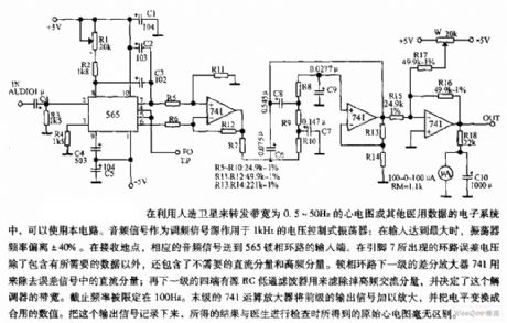
The circuit is suitable for satellite to transmit the ECG with bandwidth in 0.5 ~ 50Hz or other medical data in electronic systems. Audio signal is used as FM signal source applied to the 1KHz voltage controlled oscillator: when the input is maximum, the oscillator frequency deviation is ± 40%. In the receiving place, the corresponding audio signal is sent to the input of 565 PLL. The loop error voltage on pin 7 contains the necessary, in addition, it also contains the DC components and high-frequency components which are not necessary.
(View)
View full Circuit Diagram | Comments | Reading(3108)
EEG_WAVEFORM_ANALYZER
Published:2009/7/20 20:40:00 Author:Jessie
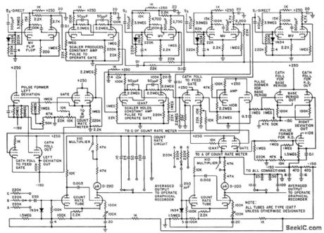
Uses derivative curves of primary eeg signals to quantitatively describe waveshape deviations of irregular electrical waveforms emitted by brain, in terms of time and amplitude. Oporates on zero-crossing detector measurements to produce analog voltages proportional to time between base periods and also proportional to time values of left and right deviation coefficients.-C. J. Zaander, Computer Ancalyzes Brain Waveforms, Electronics, 31:29, p 68-72. (View)
View full Circuit Diagram | Comments | Reading(0)
NERVE_STIMULATOR
Published:2009/7/20 20:38:00 Author:Jessie
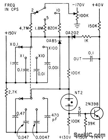
Neon relaxation oscillator and transistor give stable pulse gen erator covering range of 0.2 to 2,500 cps for neurophysiology research.-R. D. Ryan, Low-Cost Pulse Generator, Electronics, 35:15, p 70. (View)
View full Circuit Diagram | Comments | Reading(1382)
BLOOD_PRESSURE_INDICATOR
Published:2009/7/20 20:37:00 Author:Jessie
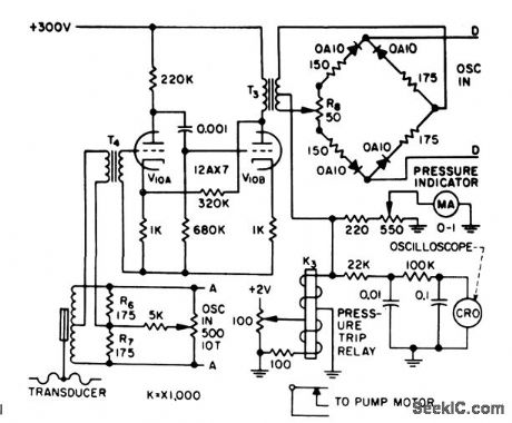
Transducer bridge is energized at points A-A by external 3-kc oscillator. Unbalance voltage is amplified by V10 and demodulated by second bridge that operates as rectifier with phase discrimination, while energized at D-D by separate 3-kc oscillator source. During unbalance, the only components reaching ring demodulator are those in phase or l80° out of phase with reference carrier voltage, giving positive or negative swing on meter-R.Schild and N. Wesson, Servo Circuit Controls Artificial Heart, Electronics, 31:15, p 73-75. (View)
View full Circuit Diagram | Comments | Reading(1017)
EEG_WAVEFORM_ZERO_DETECTOR
Published:2009/7/20 20:34:00 Author:Jessie
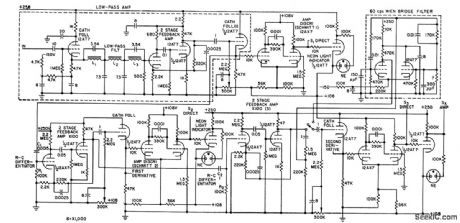
Uses Schmitt triggers to produce output of one value when input signal exceeds preset reference, and produces output of one other value when input signal is less than reference value.-C. J. Zaander, Computer Analyzes Brain Waveforms, Electronics, 31:29, p 68-72. (View)
View full Circuit Diagram | Comments | Reading(1082)
THREE_OUTPUT_3_KC_OSCILLATOR
Published:2009/7/20 20:34:00 Author:Jessie
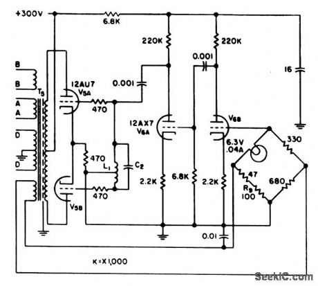
L-C oscillator provides carrier voltages of 4 V rms at 3 kc to blood-volume servo amplifier and to venous and arterial pressure indicator-Amplitude stabilization is achieved by bridge feedback network using filament-type lamp as nonlinear element in one bridge arm.-R. Schild and N. Wesson, Servo Circuit Controls Artifidal Heart, Electronics, 31:15, p 73-75. (View)
View full Circuit Diagram | Comments | Reading(696)
OSTEOGRAPH_DETECTS_BONE_DISEASE
Published:2009/7/20 20:26:00 Author:Jessie
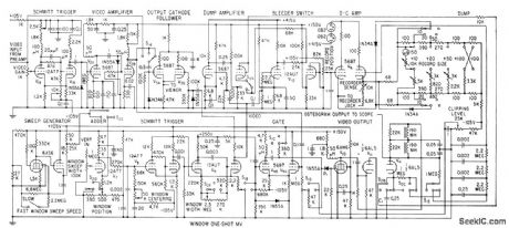
Electronic scanner using television fiying-spot microscope measures irregular micro-scopic tissue areas of spongy bone, for earlydiagnosis of bone disease. Television moni-tor receiver shows enktrged picture of bone section as ctid in centering areo to be scanned. Recorder plots ratio between bonearec and marrow area.-0. W. Jones III, R. V. Vreelcmd, and C. C. Collins, Video Microplanimeter Detects Bone Disease, Flee.tronics, 31:43, p 85-87. (View)
View full Circuit Diagram | Comments | Reading(1191)
DIELECTRIC
Published:2009/7/22 23:08:00 Author:Jessie
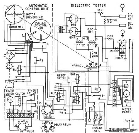
Automatic sequencing of test functions minimizes high-voltage danger to operator and improves accuracy of readings. Control system maybe inserted in any commercial high-pot tester. -F. J. Clounie, P. M. Degroat, and E. M. Szymanski, Control Makes Test Safe, Accurate, Electronics, 33:19, p 88-91. (View)
View full Circuit Diagram | Comments | Reading(805)
Two_stage_wideband_arnphfier
Published:2009/7/24 0:16:00 Author:Jessie

This circuit uses two SL550s (Fig. 2-4), with the first stage connected as a common emitter, and the second stage common base. Stable gains of up to 65 dB can be achieved by the proper selection of R1/R2. The bandwidth is 5 to 103 MHz, with a noise figure slightly greater than 2.0 dB. (View)
View full Circuit Diagram | Comments | Reading(719)
Electronic hypnotic device 2
Published:2011/8/1 2:25:00 Author:Ecco | Keyword: Electronic , hypnotic device

The electronic hypnotic device decribed in the example cangenerate simulated sound of dripping water, but also issue a low-frequency synchronized flashing signal, it is easy to reduce the tension, and the users will quickly go to sleep by listening to dripping water sound or watching flashing LED watch (LED), . The device can also be used as a stutter appliance.
The working principle.
The electronic circuit is composed of the oscillator circuit and LED drive circuit and audio circuit, andit is shownas Figure 9-139.
Oscillator circuit consists of transistors Vl, V2 and related peripheral components. LED driver circuit consists of the transistor V3 and LED VLl-VL4. Audio circuit consists of transistor V4, coupling capacitor C2, and speaker BL, volume potentiometer RW. Turning the power switch S, the oscillator circuit oscillates, the emitter of V2 outputs oscillation signal. The oscillation signal is amplified by V3 to drive VLl-VL4 shining; another path is amplified by V4 to drive speaker BL toissue the sound of dripping water. Adjusting potentiometer RP2, RPl can change the oscillator frequency, thus changing the speed of sound dripping and LED flash frequency.
(View)
View full Circuit Diagram | Comments | Reading(1015)
| Pages:1/3 123 |
Circuit Categories
power supply circuit
Amplifier Circuit
Basic Circuit
LED and Light Circuit
Sensor Circuit
Signal Processing
Electrical Equipment Circuit
Control Circuit
Remote Control Circuit
A/D-D/A Converter Circuit
Audio Circuit
Measuring and Test Circuit
Communication Circuit
Computer-Related Circuit
555 Circuit
Automotive Circuit
Repairing Circuit
