
Control Circuit
Index 312
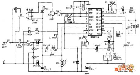
Based on HT7610A/HT7611A Relay Drive Circuit Diagram
Published:2011/3/21 4:18:00 Author:Nicole | Keyword: Relay Drive
View full Circuit Diagram | Comments | Reading(2597)
Automatic dimming light circuit
Published:2011/3/21 1:49:00 Author:Joan | Keyword: Automatic dimming light, dimming light

Lamp dimmer. The figure below shows the circuit can be used for lamp dimming. It uses a small quantity of components, which can be installed inside the lamp seat. The circuit is commonly used in RC phase shift circuit. W can be adjusted to change the triac conduction angle, which changes the lamp brightness. KS is a bi-directional trigger diode. C2 and L are anti-jamming devices. You can simplify the circuit if you do not ask more, such as reducing components, eliminating C2 and L2.
(View)
View full Circuit Diagram | Comments | Reading(1363)
Games infrared remote control schematic
Published:2011/3/21 3:23:00 Author:Joan | Keyword: Games infrared remote control
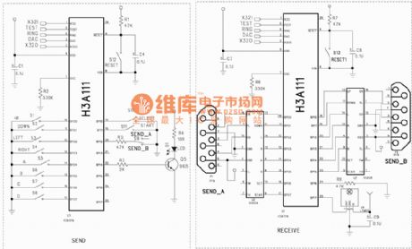
Above is Games infrared remote control schematic. (View)
View full Circuit Diagram | Comments | Reading(568)
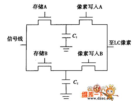
Single Pixel Drive Circuit Diagram
Published:2011/3/20 22:42:00 Author:Nicole | Keyword: Single Pixel Drive
View full Circuit Diagram | Comments | Reading(354)
Intelligent pressure measurement and control circuit
Published:2011/3/18 2:06:00 Author:Joan | Keyword: Intelligent, pressure measurement and control
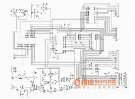
The figre is the Intelligent pressure measurement and control circuit. (View)
View full Circuit Diagram | Comments | Reading(430)
Complementary dimming circuit
Published:2011/3/20 22:24:00 Author:Joan | Keyword: Complementary , dimming

Complementary dimming circuitComplementary dimming circuit is shown in Figure 1-5, the circuit consists of two dimming circuit of which R1, C3, L are the axises of symmetry. W can be adjusted gradually to make a bright light, while the other light gradually dims. However, the total brightness of the two lamps is constant. This circuit is useful in certain situations.
(View)
View full Circuit Diagram | Comments | Reading(528)
Triple key interlock electronic switch schematic
Published:2011/3/17 19:59:00 Author:Joan | Keyword: Triple key, interlock , electronic switch

The figure is Triple key interlock electronic switch schematic.
(View)
View full Circuit Diagram | Comments | Reading(2913)
| Pages:312/312 At 20301302303304305306307308309310311312 |
Circuit Categories
power supply circuit
Amplifier Circuit
Basic Circuit
LED and Light Circuit
Sensor Circuit
Signal Processing
Electrical Equipment Circuit
Control Circuit
Remote Control Circuit
A/D-D/A Converter Circuit
Audio Circuit
Measuring and Test Circuit
Communication Circuit
Computer-Related Circuit
555 Circuit
Automotive Circuit
Repairing Circuit