Index 13
STATION STOP
Published:2013/6/21 3:01:00 Author:muriel | Keyword: STATION STOP
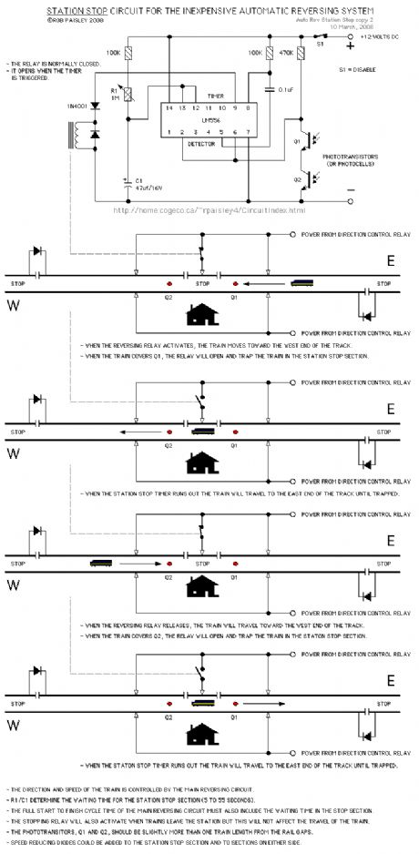
This circuit will stop and start the train at a station located on the reversing track.
This circuit is as simple as possible, using the bottom section of a 556 timer as a photodetector and the top section as the delay timer.
The timing circuit takes its control and track power from the power supply circuit on this page.
NOTE: When using this circuit, there are other things to consider, such as; train length and whether the locomotive has all wheel pickup. These can affect the placement of the gaps and phototransistors. (View)
View full Circuit Diagram | Comments | Reading(1006)
PSEUDO SPEED CONTROL
Published:2013/6/21 3:00:00 Author:muriel | Keyword: PSEUDO SPEED CONTROL
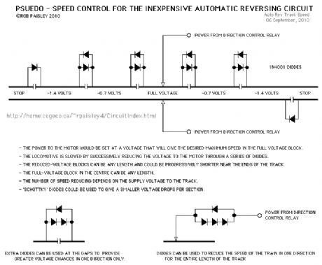
This track circuit uses diodes and gaps to provide a crude form of speed control. (View)
View full Circuit Diagram | Comments | Reading(764)
Alternate Location Control
Published:2013/6/21 2:53:00 Author:muriel | Keyword: Alternate Location Control
View full Circuit Diagram | Comments | Reading(826)
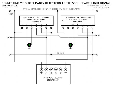
556 - Searchlight Signal Driver
Published:2013/6/21 2:51:00 Author:muriel | Keyword: 556 , Searchlight Signal , Driver
View full Circuit Diagram | Comments | Reading(718)
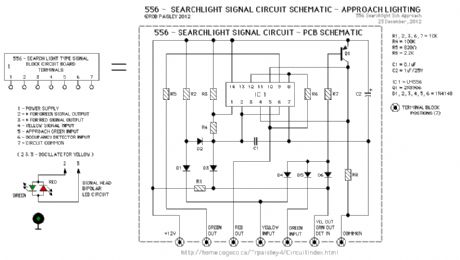
556 - Searchlight Signal Driver Schematic
Published:2013/6/21 2:50:00 Author:muriel | Keyword: 556, Searchlight Signal , Driver Schematic
View full Circuit Diagram | Comments | Reading(1061)
PIC 16F628 MiniDCC© Controller Circuit Schematic
Published:2013/6/21 2:46:00 Author:muriel | Keyword: PIC 16F628, MiniDCC© , Controller Circuit Schematic
View full Circuit Diagram | Comments | Reading(1253)
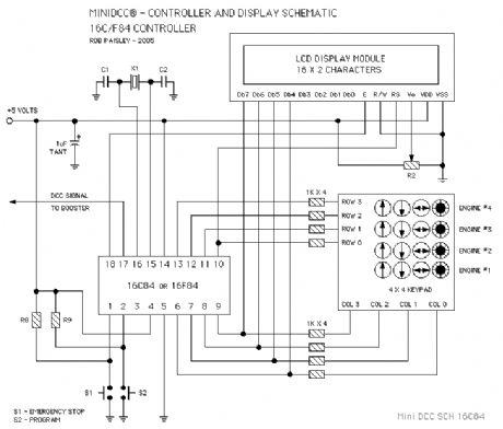
PIC 16C84 MiniDCC© Controller Circuit Schematic
Published:2013/6/21 2:46:00 Author:muriel | Keyword: PIC 16C84, MiniDCC©, Controller Circuit Schematic
View full Circuit Diagram | Comments | Reading(848)
6 Aspect - Searchlight Signal Driver (LM555)
Published:2013/6/18 21:40:00 Author:muriel | Keyword: 6 Aspect, Searchlight Signal Driver , LM555

The circuit on this page is a 6 Aspect driver for a bicolour LED type Searchlight Signal. The available signal indications are; SOLID - RED, YELLOW, GREEN, and FLASHING - RED, YELLOW and GREEN. The circuit can also turn the signal OFF for approach lighting if desired.
As this is a driver circuit, there is no actual input logic to select the signal indication. This will be added when it has been worked out.
If you have any ideas on how such a logic system might function might work, please send an email with any details.
The first circuit on this page is controlled by four toggle switches. Refer to the tables on the diagram for switch positions and the resulting signal indications. (View)
View full Circuit Diagram | Comments | Reading(865)
Basic Transistor Switches
Published:2013/6/18 21:03:00 Author:muriel | Keyword: Basic Transistor, Switches
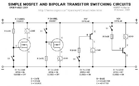
MOSFET and Bipolar transistors are often used for high speed switching applications. Below are four very simple examples of this.
ON-OFF toggle switches are used in place of an electronic control circuit. (View)
View full Circuit Diagram | Comments | Reading(1215)
CA4060B Timer Circuits
Published:2013/6/18 20:49:00 Author:muriel | Keyword: CA4060B, Timer Circuits
View full Circuit Diagram | Comments | Reading(991)
Push Button Motor Control Circuit - 3
Published:2013/6/18 3:57:00 Author:muriel | Keyword: Push Button Motor, Control Circuit
View full Circuit Diagram | Comments | Reading(1500)
Push Button Motor Control Circuit - 2
Published:2013/6/18 3:57:00 Author:muriel | Keyword: Push Button Motor , Control Circuit
View full Circuit Diagram | Comments | Reading(1878)
Push Button Motor Control Circuits
Published:2013/6/18 3:56:00 Author:muriel | Keyword: Push Button, Motor, Control Circuits
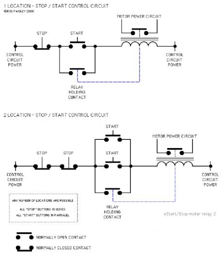
The circuits on this page are for motor controls using Push buttons and would typically be found in commercial and industrial installations.
The circuits do not show the wiring of the motors themselves as this depends on the particular motor type. The type of motor also governs the number of contacts needed for the motor side of these circuits.
The Relay Holding Contacts and the Interlock Contacts shown in these circuit would normally be built into the motor control relays. (View)
View full Circuit Diagram | Comments | Reading(2059)
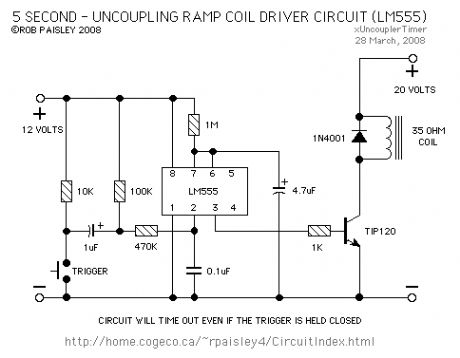
Timed Uncoupling Ramp Driver (LM555)
Published:2013/6/18 3:53:00 Author:muriel | Keyword: Timed Uncoupling Ramp Driver , LM555
View full Circuit Diagram | Comments | Reading(960)
Special Function Timer 4
Published:2013/6/18 3:49:00 Author:muriel | Keyword: Special Function Timer
View full Circuit Diagram | Comments | Reading(825)
Special Function Timer 3
Published:2013/6/18 3:49:00 Author:muriel | Keyword: Special Function Timer
View full Circuit Diagram | Comments | Reading(732)
Special Function Timer Circuits (LM555) 2
Published:2013/6/18 3:49:00 Author:muriel | Keyword: Special Function Timer
View full Circuit Diagram | Comments | Reading(888)
Special Function Timer Circuits (LM555) 1
Published:2013/6/18 3:49:00 Author:muriel | Keyword: Special Function , Timer Circuits, LM555
View full Circuit Diagram | Comments | Reading(955)
Special Function Timer Circuits (LM555)
Published:2013/6/18 3:48:00 Author:muriel | Keyword: Special, Function Timer Circuits , LM555
View full Circuit Diagram | Comments | Reading(1044)
High Side Current Monitor Specific IC
Published:2013/6/18 3:46:00 Author:muriel | Keyword: High Side , Current Monitor , Specific IC
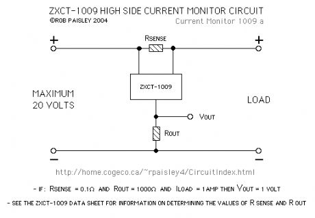
The next circuit uses an integrated circuit that is specifically designed for this application. There are a number of manufactures of these devices and there is also a considerable variety of features that can be had from specific IC's.
Due to the internal circuitry of this device, no diodes are required in the supply circuit. (View)
View full Circuit Diagram | Comments | Reading(1036)
| Pages:13/312 1234567891011121314151617181920Under 20 |
Circuit Categories
power supply circuit
Amplifier Circuit
Basic Circuit
LED and Light Circuit
Sensor Circuit
Signal Processing
Electrical Equipment Circuit
Control Circuit
Remote Control Circuit
A/D-D/A Converter Circuit
Audio Circuit
Measuring and Test Circuit
Communication Circuit
Computer-Related Circuit
555 Circuit
Automotive Circuit
Repairing Circuit

