Time Control
Index 6
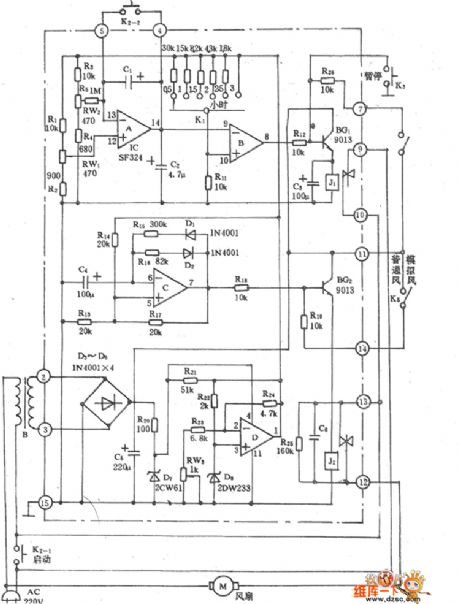
Electric Fan Natural Wind Timing Control Circuit
Published:2011/4/23 1:08:00 Author:Robert | Keyword: Electric Fan, Natural Wind, Timing Control

Electric Fan Natural Wind Timing Control Circuit is shown below:
(View)
View full Circuit Diagram | Comments | Reading(598)
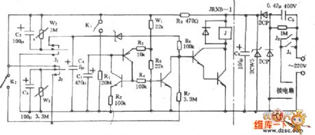
Electric Fan Multi-Function Timing Control Circuit
Published:2011/4/23 1:05:00 Author:Robert | Keyword: Electric Fan, Multi-Function Timing Control

Electric Fan Multi-Function Timing Control Circuit is shown below:
(View)
View full Circuit Diagram | Comments | Reading(615)
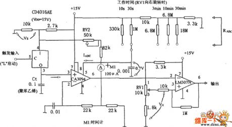
Long Time Timing Circuit (LM307N/CA3094)
Published:2011/4/21 7:00:00 Author:Robert | Keyword: Long Time Timing

Long Time Timing Circuit (LM307N/CA3094) is shown below. This circuit uses the discharge of the controllable operational amplifier CA3094 to make a long time timing, generally change he VH via RV1, to achieve the goal of change the timing continuously.
(View)
View full Circuit Diagram | Comments | Reading(710)
4h Timing circuit composed of 556
Published:2011/4/14 3:42:00 Author:Ecco | Keyword: 4h , Timing circuit

The figure shows 4h timing circuit which is composed of 556 dual time base circuit. To access N8281 divider network in the middle of 556 dual time base circuit, it will get a long time delay without large volume of capacitors. The first l / 2 (556) works in the way of oscillator, the period is l / f. It will produce the signal output in a N / f cycle to trigger the other half 1 / 2 (556) to add the output of oscillator to N divider network. It decides the total delay produced by the dividerto connect the divider to ⑧ pin of the second 1 / 2 (556) input terminal. Delay time is divided in 4 blocks of 30min, 1h, 2h, 4h. If connecting N8281 crossover in series additionally , the total amount of delay can be increased to days or even weeks.
(View)
View full Circuit Diagram | Comments | Reading(1789)
The precise timing circuit for correcting capacitor tolerance
Published:2011/4/20 3:32:00 Author:Ecco | Keyword: precise , timing circuit , correcting , capacitor tolerance
View full Circuit Diagram | Comments | Reading(489)
The school bell timing circuit diagram
Published:2011/4/10 20:20:00 Author:Ecco | Keyword: school bell timing

General school bell is pulled by the people, but it is difficult to control the tone time. It can solve this problem by installing a timer to control ring. Working principle is shown in Figure 213: To press the button QA when pulling the bell, the time relay SJ pulls, bell ring tone is also energized, to release the button QA, as the SJ pulls, SJ normally open point is self-hold until time relay seting time(time relay could adjust to 1 minute or according to the choice), the delay normally closed point is cut off and make time relay loses electric and releases, SJ normally open point is cut off, the tone will stop.
(View)
View full Circuit Diagram | Comments | Reading(872)
Fan cycle timer circuit
Published:2011/3/22 3:33:00 Author:may | Keyword: Fan cycle timer

Fan cycle timer circuit is shown in the following diagram:
(View)
View full Circuit Diagram | Comments | Reading(1228)
The exposure time control circuit diagram
Published:2011/3/30 21:49:00 Author:Ecco | Keyword: Time exposure

To assure the quality of the photogragh, this device can satisfy the shutterbug to control the time of exposure. It has the advantages of high accuracy in time controlling, having universal function such as time exposure, light-dimmer, pressure regulating and so on. Enlarging bulb or iron, electric blanket and lamp. The electric applianceses, such as electric fan and dynamo. etc. can be connected to the output socket CZ, and the output is controlled by the silicon capacity. For example, the pure resistive load can provide the power with 600 W; capacitive or inductive burden make the output be smaller than 300w.
(View)
View full Circuit Diagram | Comments | Reading(556)
| Pages:6/6 123456 |
Circuit Categories
power supply circuit
Amplifier Circuit
Basic Circuit
LED and Light Circuit
Sensor Circuit
Signal Processing
Electrical Equipment Circuit
Control Circuit
Remote Control Circuit
A/D-D/A Converter Circuit
Audio Circuit
Measuring and Test Circuit
Communication Circuit
Computer-Related Circuit
555 Circuit
Automotive Circuit
Repairing Circuit
