
Protection Circuit
Index
The motor protection circuit with leakage relay
Published:2013/4/3 3:56:00 Author:Ecco | Keyword: motor protection
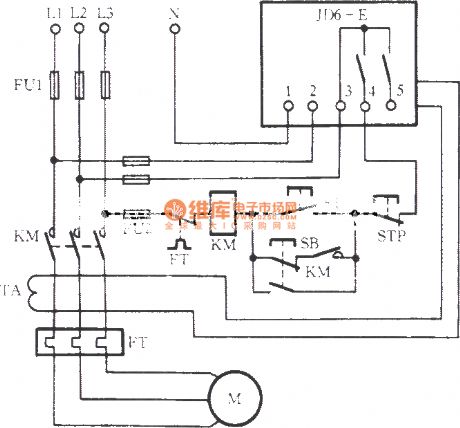
The motor protection circuit with leakage relay is shown as figure.
(View)
View full Circuit Diagram | Comments | Reading(1162)
Logic overvoltage protection
Published:2013/3/20 1:56:00 Author:Ecco | Keyword: Logic overvoltage protection
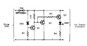
Zener diode ZD1 senses the power supply voltage, and if the supply voltage rise above 6 V, Q1 will-turn on. Therefore, Q2 conducts short the rail. Next events depend on the source supply. It will either shut down, go into current-limit or blow its supply fuse. None of these will damage the TTL chips. The rating of Q2 depends on the source supply, and whether it will be required to operate continuously in the event of failure. Its current rating has to be in excess of the source supply.
(View)
View full Circuit Diagram | Comments | Reading(1264)
PWM inverter over-current protection circuit diagram
Published:2012/12/12 2:51:00 Author:Ecco | Keyword: PWM inverter , over-current protection
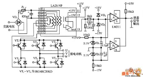
It can prevent IGBT or MOSFET output stage from being damaged by large current flowing. The maximum current is 23A when the motor is overcurrent, and the overcurrent needs 3μs flowing to protection circuit.
(View)
View full Circuit Diagram | Comments | Reading(2569)
△ connection motor zero sequence voltage relay phase failure protection circuit
Published:2012/12/4 20:47:00 Author:Ecco | Keyword: △ connection, motor, zero sequence, voltage relay, phase failure, protection
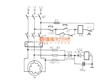
In the circuit shown in figure, three resistors R1 ~ R3 are connected as an artificial neutral point, when the motor is off-phase, the neutral point shifts, relay K is energized, the normally closed contact gets action to cut KM coil loop, KM loses power and releases, thereby protecting the motor.
(View)
View full Circuit Diagram | Comments | Reading(2731)
The amplifier tube protector circuit
Published:2012/12/2 21:55:00 Author:Ecco | Keyword: Amplifier tube , protector

In the Figure, K is a power switch, T1 is the controlling small power transformer, T2 is the amplifier power transformer. IC1 (S1-S4) is the four - way analog switch CD4066. When the machine is open, K1 is closed, C1 gets 12V DC voltage. The S3 gets conduction because control terminal is high, then S4 control terminal is pulled low, S4 disconnects. C2 voltage can not get mutation, so S1 gets conduction when machines is open due to the control terminal is in high level, and optocoupler IC2 LED is lit.
(View)
View full Circuit Diagram | Comments | Reading(1666)
Input protection circuit of broadband strain signal conditioner 1B31
Published:2012/11/23 2:56:00 Author:Ecco | Keyword: Input protection , broadband strain , signal conditioner

In the industrial field measurements, the 1B31 is needed to be designed input protection circuit to protect input end from instantaneous short-circuit and damage caused by 220V AC power accident. Input protection circuit is shown in the figure. It selects FDH333 diode with high conductivity and low leakage current, and 1N963 voltage regulator tube forms bi-directional parallel input limiting circuit, the input voltage can be clamped to a ± 12. 5V range. FDH333 average rectifier current is 200mA, reverse voltage is 125V, reverse-leakage current is only 1nA, maximum pressure drop can be up to 1. 0V, junction Capacitance is 6. 0pF.
(View)
View full Circuit Diagram | Comments | Reading(698)
Refrigerator automatic protector
Published:2012/11/21 21:05:00 Author:Ecco | Keyword: Refrigerator, automatic protector


BT33 forms a delay circuit. When the power is turned on, the relay J1 does not work, contact J1-2 disconnects for five minutes, due to the charging voltage rise of the capacitor C1, BT33 gets conduction, relay J1 pulls, J1 -2 contact gets closure, then the refrigerator gets power, which is protected by J1-1 normally open contact. Under the case with normal voltage, D2, BG2 get conduction, D3, and D4, and BG3 are cutoff, relay J2 does not work.
(View)
View full Circuit Diagram | Comments | Reading(1730)
Water tower automatic water supply protection circuit
Published:2012/11/20 2:21:00 Author:Ecco | Keyword: Water tower , automatic water supply rotection
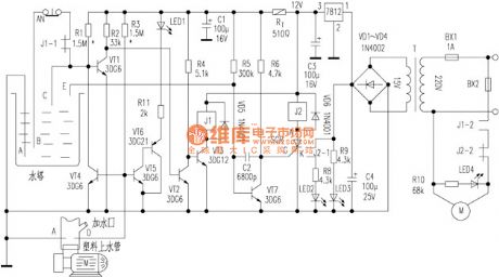
VT1, VT2, VT3, J1 are the main components of the pumping circuit, the working principle is not difficult to make a self- analysis for reader. Water protection circuit is mainly composed of the probe D and VT4, if the pumping time interval is too long, the tube memory water leakage is below D, and the water circuits A , D are open, VT4 gets saturated conduction, so that VT1 base pole clamp is at low potential. When the towers level falls to the lower limit B or less, due to the extremely low level of VT1 base, it can not be turned and therefore can not pumping.
(View)
View full Circuit Diagram | Comments | Reading(1383)
The neutral point voltage open phase voltage relay protection circuit
Published:2012/11/14 19:52:00 Author:Ecco | Keyword: neutral point, voltage, open phase, voltage relay, protection

When any one phase of the motor three-phase power supply loses power, if the motor uses Y connection, wherein the neutral point (midpoint) voltage will be significantly improved. Therefore, the midpoint voltage can be used as off -phase fault signal. As shown in figure, the circuit uses voltage relay for protection device.
(View)
View full Circuit Diagram | Comments | Reading(1790)
Resistance-capacitance phase protection circuit
Published:2012/11/14 19:34:00 Author:Ecco | Keyword: Resistance-capacitance , phase protection

The circuit shown in Figure uses negative sequence voltage generated by unbalanced three-phase power for phase-failure protection. When the three-phase power is symmetric and line voltage has mutual lag 120°electrical angle, the voltage across the relay KV voltage is 0V, so KV has no action. When the three-phase power loses a phase, the voltage is applied to the ends of the coil, KV pulls in, and its normally open contact action to turn on KM2 coil loop, then the normally closed contact KM2 action, KM1 cuts the power supply of motor M.
(View)
View full Circuit Diagram | Comments | Reading(2909)
△ connection motor phase failure voltage relay protection circuit
Published:2012/11/14 20:18:00 Author:Ecco | Keyword: △ connection, motor , phase failure, voltage relay protection

For △ connection motor, you must add neutral point, that is, three Y-shaped capacitors are connected ( impedance element ) with the motor in parallel, then the neutral point of Y shape is connected to the relay protection element, and it is shown in figure. During normal operation of the motor phase power supply, the neutral point voltage U00 is typically less than 10V.
(View)
View full Circuit Diagram | Comments | Reading(1795)
EOCR motor protection circuit
Published:2012/11/12 20:27:00 Author:Ecco | Keyword: EOCR , motor protection


EOCR is Korea SAMWHA 's new motor protector with a microprocessor, , there are two popular kinds of EOCR-SS type EOCR-3DD in the market. Wiring diagram is shown in Figure 2.
(View)
View full Circuit Diagram | Comments | Reading(2300)
The motor overheating and influent protection circuit
Published:2012/11/12 20:39:00 Author:Ecco | Keyword: motor , overheating , influent protection

Before the burned-out motor damage, its winding temperature rises high; in many occasions, motor is easily bilging, resulting in burned. The circuit is shown in Figure. It can prevent overheating influent accidents. RT is a positive temperature coefficient thermistor (PTC); M, N are plastic insulated wires which are closed and buried in the motor stator windings, and their heads are stripped, they are used for detecting the motor inlet.
(View)
View full Circuit Diagram | Comments | Reading(3223)
The overvoltage protection circuit
Published:2012/10/31 21:21:00 Author:Ecco | Keyword: Overvoltage protection

When the external voltage does not exceed the set E voltage Vs, negative resistance light-emitting diode VD1 it cutoff, VT is cutoff because of no base current, relay J does not pull in, and its normally closed contact J1-1 is closed to provide supply for the load RL. Once the external voltage E exceeds the set voltage Vs, VD1 gets conduction, VD1 emitting light to show overvoltage. The the capacitor C1 connected to VD1 in parallel is anti - electromagnetic interference, and it can be selected in the range of 0.01μF ~ 0.1μF.
(View)
View full Circuit Diagram | Comments | Reading(1280)
Input current protection circuit diagram using INA321/322
Published:2012/10/17 21:14:00 Author:Ecco | Keyword: Input current , protection

INA321/322 input end's interior has electrostatic discharge (ESD) protection diode, and the protection diode will get conduction when the input voltage exceeds the supply voltage 500mV, then RLIM will limit the input current ( 10mA ) to play a role in the protection circuit. Many input signals have limited streaming capabilities, at the time, the current limiting resistor RLIM can be ignored.
(View)
View full Circuit Diagram | Comments | Reading(683)
Battery cold junction thermocouple protection circuit
Published:2012/10/16 22:31:00 Author:Ecco | Keyword: Battery, cold junction , thermocouple protection

K thermocouple end is placed is insulation block, the thermocouple junction ambient temperature is continuously controlled by IN914 diode. The diode correct hermoelectromotive force generated on junction by feedback voltage. Then it is sent to the op amp by 1.5MΩ and 475Ω resistors. The thermocouple junction is pulled in zero ice water during calibration. Tuning 500Ω can make output be zero pressure; then the thermocouple is inserted in 250 ℃ furnace, tune range for output is 2.50V. In 9 ~ 250 ℃ range, the accuracy of K thermal couple is ± 3 ℃.
(View)
View full Circuit Diagram | Comments | Reading(1815)
Polarity protection circuit
Published:2012/9/19 21:18:00 Author:Ecco | Keyword: Polarity protection

The most simple polarity protection tehnique is to connect a series diode to the power line input. The diode conducts only when the power supply protection is correct. But the incovenient is that at higher current levels, the voltage drops and power loss of the diode affects the power level adversely.This polarity protection circuit is dimensioned for 12 V power supplies and avoids the voltage and power loss problem. By correct polarity, the current flowing to the D1 and the relay coil causes the relay contacts to activate. The NO contact closes powering the electronic device. The NC contact opens and the current supplying the relay coil is reduced to a low level just enough to maintain relay activation.
Polarity protection circuit schematic
When reversed polarity occurs, the diode blocks the current and the relay cannot activate. The NO contact remains open and the electronic device is protected from the reversed polarity voltage.
3 Responses to “Polarity protection circuit”
Source: electroschematic.com (View)
View full Circuit Diagram | Comments | Reading(1192)
Speaker protection circuit
Published:2012/9/17 1:19:00 Author:Ecco | Keyword: Speaker, protection circuit

The speaker protection circuit is shown in the figure. It has the left and right channels to work independently. In the Figure ( left channel ), R2 , C4, VT2 and VT3 form a starting up delay circuit to prevent the starting up high-current impact on speaker.
Components Selection: LED can choose Φ3mm high-brightness color LED. Since LED current may be high or low, the parameters of R5, R9 can be slightly adjusted. At the same time, the LED and the current limit resistors R5, R9 are connected to two ends of relays RE1 and RE2 in parallel to inhibit the anti-peak voltage and prevent the breakdown from VT2, VT3, VT5 and VT6. C4, C9 should use low-leakage tantalum capacitors. Other components parameters are shown in the figure.
(View)
View full Circuit Diagram | Comments | Reading(4229)
Open-phase protection circuit using three current transformers
Published:2012/9/12 2:14:00 Author:Ecco | Keyword: Open-phase protection , three current transformers

As shown in figure, 1TA, 2TA and3TAin circuit are three current transformers, andtheir secondary circuit are connetcedin parallel, then the loop is connected to a current relay KA. Duringthe motor M is in normal operation, KA does not operate. When there is a phase failure, zero-sequence current is approximately 1.73 times ofthe rated current, then KA acts tocut off the power for motor.
(View)
View full Circuit Diagram | Comments | Reading(2688)
Overload speaker protection circuit
Published:2012/9/10 20:56:00 Author:Ecco | Keyword: Overload speaker, protection

The circuit input is taken from the terminal loudspeaker or amplifier output jacks. If the right channel is large enough to charge C1 to a potential which exceeds the breakdown voltage of the emitter of Ql, a voltage pulse appears in R7. Similarly, if the left channel signal is large enough to charge C2 to a voltage that is greater than the breakdown voltage of the emitter of Q2 , a pulse appears in R7. The pulse triggers in R7 5CRI. A door sensitive SCR (LGT less than 15 RNA or IGT is the gate-trigger current) that locks in a conducting state and energizes Ryl. The action of the relay will interrupt the speaker circuit. and silence follows you must alert on the problem.
Source: discovercircuits (View)
View full Circuit Diagram | Comments | Reading(1880)
| Pages:1/12 123456789101112 |
Circuit Categories
power supply circuit
Amplifier Circuit
Basic Circuit
LED and Light Circuit
Sensor Circuit
Signal Processing
Electrical Equipment Circuit
Control Circuit
Remote Control Circuit
A/D-D/A Converter Circuit
Audio Circuit
Measuring and Test Circuit
Communication Circuit
Computer-Related Circuit
555 Circuit
Automotive Circuit
Repairing Circuit