Protection Circuit
The overvoltage protection circuit
Published:2012/10/31 21:21:00 Author:Ecco | Keyword: Overvoltage protection | From:SeekIC
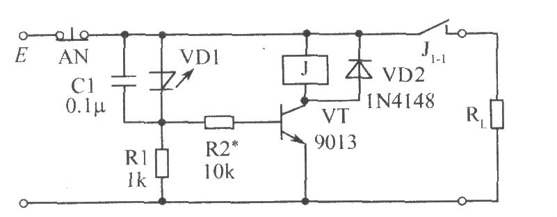
When the external voltage does not exceed the set E voltage Vs, negative resistance light-emitting diode VD1 it cutoff, VT is cutoff because of no base current, relay J does not pull in, and its normally closed contact J1-1 is closed to provide supply for the load RL. Once the external voltage E exceeds the set voltage Vs, VD1 gets conduction, VD1 emitting light to show overvoltage. The the capacitor C1 connected to VD1 in parallel is anti - electromagnetic interference, and it can be selected in the range of 0.01μF ~ 0.1μF.
Reprinted Url Of This Article:
http://www.seekic.com/circuit_diagram/Control_Circuit/Protection_Circuit/The_overvoltage_protection_circuit.html
Print this Page | Comments | Reading(3)

Article Categories
power supply circuit
Amplifier Circuit
Basic Circuit
LED and Light Circuit
Sensor Circuit
Signal Processing
Electrical Equipment Circuit
Control Circuit
Remote Control Circuit
A/D-D/A Converter Circuit
Audio Circuit
Measuring and Test Circuit
Communication Circuit
Computer-Related Circuit
555 Circuit
Automotive Circuit
Repairing Circuit
Code: