Index 92
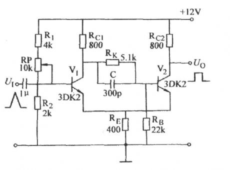
Emitter-coupled bistable circuit with changable action of circuit
Published:2011/10/18 21:57:00 Author:Ecco | Keyword: Emitter-coupled bistable , changingable action
View full Circuit Diagram | Comments | Reading(969)
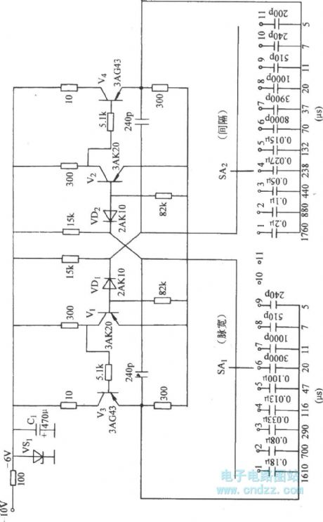
Astable circuit with sub-file adjusting pulse width
Published:2011/10/18 22:06:00 Author:Ecco | Keyword: Astable circuit , sub-file adjusting , pulse width
View full Circuit Diagram | Comments | Reading(594)
The winding tap T- connection three-speed circuit of single-phase motor
Published:2011/12/7 20:51:00 Author:Ecco | Keyword: winding tap , T- connection , three-speed , single-phase motor
View full Circuit Diagram | Comments | Reading(2598)
The winding tap L-2 connection three-speed circuit of single-phase motor
Published:2011/12/7 20:53:00 Author:Ecco | Keyword: winding tap , connection , three-speed circuit , single-phase motor
View full Circuit Diagram | Comments | Reading(3626)
The structure of ultrasonic sensor
Published:2011/9/16 0:58:00 Author:Rebekka | Keyword: structure, ultrasonic sensor
View full Circuit Diagram | Comments | Reading(1030)
6Y7 Monolithic automatic voltmeter
Published:2011/9/15 21:16:00 Author:Rebekka | Keyword: Monolithic automatic voltmeter
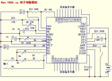
Overview:1. Low power consumption: We hope two ordinary button battery can be used for half an year.2. Low voltage: It does not use bulky batteries such as 5 # battery or tandem structure.3. High precision: It owns 31/2 or more precision.4. High stability: It requires a good reading stability.5. Low-cost: The cost of chip is lower than RMB10.00.6. Automatic: Fool-type operation.7. Monolithic: It does not use other active devices such as reference power and thermistor etc.That is these requirements produce the following design requirements.1. Use ordinary digital circuits manufacturing chip.2. Precision reference supply.3. Precision comparator.4. Precision Rectifier.5. 3V power supply.6. Working current is lower than 1MA.7. Analog / digital conversion.8. The least amount of external adjustment.
(View)
View full Circuit Diagram | Comments | Reading(811)
Optocoupler level conversion circuit diagram
Published:2011/9/27 20:56:00 Author:Rebekka | Keyword: Optocoupler level conversion
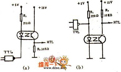
For different level conversion circuits, or input, output circuits , ifits levelneeds to be separated, it is more convenient to use optical couplers.Figures(a) and (b) circuits are 5V power supply TTL IC and 15V power supply HTL IC. Each circuit is connected and conducted level.
In figure (a), when TTL gate circuit turns on, it outputs low level, then the light-emitting diode turns on, phototransistor outputs high level; TTL gates close, then the light-emitting diode cuts off, phototransistor outputs low level. In figure (b),it uses TTL outputs high level, light-emitting diode turns on, photo transistor outputs low level; TTL conduction outputs low level, then LED isoff, and phototransistor outputs high level. (View)
View full Circuit Diagram | Comments | Reading(1881)
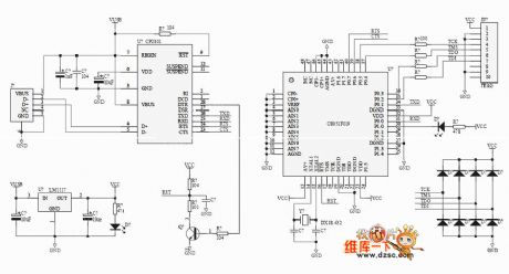
C8051F EC2 JTAG emulator circuit diagram
Published:2011/12/9 0:50:00 Author:Ecco | Keyword: JTAG emulator
View full Circuit Diagram | Comments | Reading(2164)
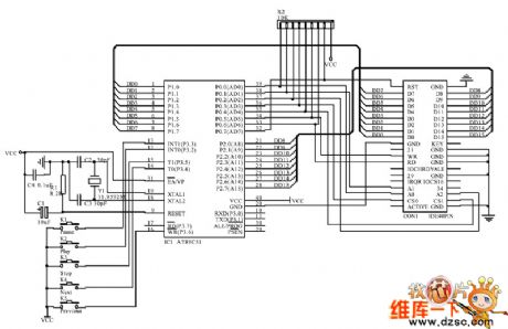
CD-ROM interface schematic circuit diagram
Published:2011/12/9 0:49:00 Author:Ecco | Keyword: CD-ROM interface , schematic
View full Circuit Diagram | Comments | Reading(3066)
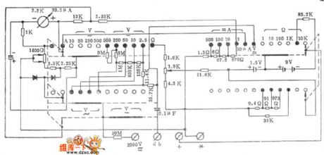
The high-performance 500 multimeter circuit diagram
Published:2011/12/9 0:49:00 Author:Ecco | Keyword: high-performance , multimeter
View full Circuit Diagram | Comments | Reading(1032)
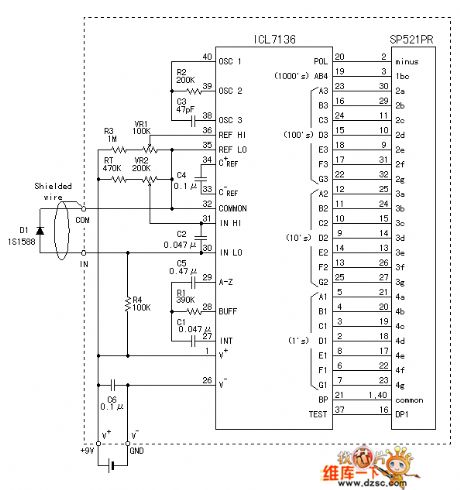
The LCD digital thermometer circuit using 7136
Published:2011/12/8 20:43:00 Author:Ecco | Keyword: LCD digital thermometer
View full Circuit Diagram | Comments | Reading(1512)
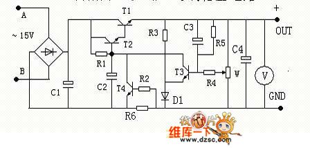
Adjustable voltage-stabilizing circuit with current limiting protection function
Published:2011/12/8 20:51:00 Author:Ecco | Keyword: Adjustable , voltage-stabilizing circuit , current limiting, protection function
View full Circuit Diagram | Comments | Reading(759)
Memory internal memory circuit diagram
Published:2011/12/8 20:20:00 Author:Ecco | Keyword: Memory , internal memory
View full Circuit Diagram | Comments | Reading(772)
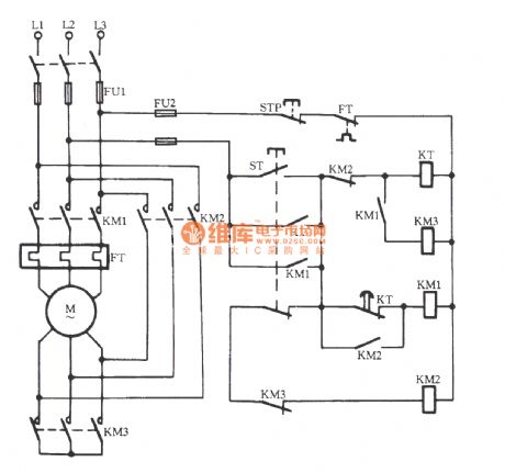
The Y-△ starting circuit 3 for motor without power switch
Published:2011/11/3 2:06:00 Author:Ecco | Keyword: Y-△ starting , motor , without power switch
View full Circuit Diagram | Comments | Reading(653)
JJ2B-30 ~ 90 Variable voltage start-up circuit
Published:2011/12/7 2:08:00 Author:Ecco | Keyword: Variable voltage, start-up circuit
View full Circuit Diagram | Comments | Reading(598)
JJ28-11 ~ 22 Variable voltage start-up circuit
Published:2011/12/7 2:11:00 Author:Ecco | Keyword: Variable voltage , start-up
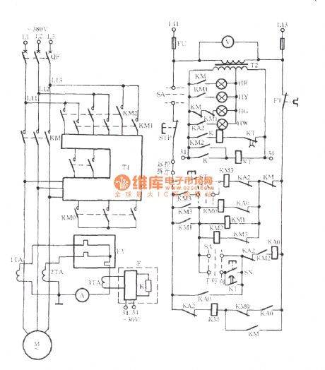
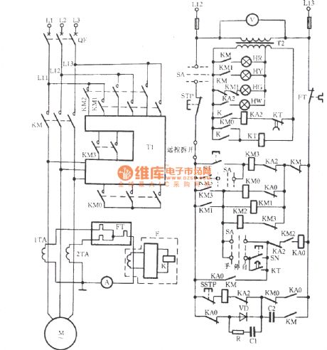
This starter is suitablefor 11 ~ 22kW motor.Because the current islarge,it uses three current transformers E to provide mutual inductance current.
(View)
View full Circuit Diagram | Comments | Reading(659)
JJ1B-75 Autoformer step-down start circuit
Published:2011/12/7 2:12:00 Author:Ecco | Keyword: Autoformer, step-down start
View full Circuit Diagram | Comments | Reading(625)
LOGO module controlling autotransformer step-down start circuit
Published:2011/12/7 2:06:00 Author:Ecco | Keyword: LOGO module , controlling , autotransformer , step-down start
View full Circuit Diagram | Comments | Reading(1289)
QX3-13 Y-△ buck starter
Published:2011/12/7 1:54:00 Author:Ecco | Keyword: Y-△ buck Starter
View full Circuit Diagram | Comments | Reading(812)
First-order bypass filter
Published:2011/12/6 1:49:00 Author:Ecco | Keyword: First-order , bypass filter

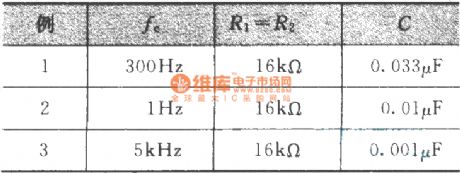
Design value Example :
(View)
View full Circuit Diagram | Comments | Reading(823)
| Pages:92/471 At 2081828384858687888990919293949596979899100Under 20 |
Circuit Categories
power supply circuit
Amplifier Circuit
Basic Circuit
LED and Light Circuit
Sensor Circuit
Signal Processing
Electrical Equipment Circuit
Control Circuit
Remote Control Circuit
A/D-D/A Converter Circuit
Audio Circuit
Measuring and Test Circuit
Communication Circuit
Computer-Related Circuit
555 Circuit
Automotive Circuit
Repairing Circuit
