Index 46
Hall Sensor Amplifier Circuit
Published:2011/7/15 6:24:00 Author:Sue | Keyword: Hall, Sensor, Amplifier

C1: use low-leakage capacitor.
I: capacitor's leakage current(DC).
(a) be influenced by capacitor's leakage current. (View)
View full Circuit Diagram | Comments | Reading(2571)
Instrumentation Amplifier Circuit with Program Controlled Integrated Operational Amplification
Published:2011/7/18 7:10:00 Author:Sue | Keyword: Instrumentation Amplifier, Program Controlled, Integrated, Operational Amplification

The circuit uses program controlled operational amplifier F4250 as amplifier, which has a low static power. The power voltage is ±1.5V, which can use two dry batteries. The main features of the circuit: Every input terminal's input resistance value over the ground is 100MΩ. Input bias current is 0.2nA. Working current is 2.8μA. Power consumption is 8.4μW. The circuit voltage gain is 100. The circuit alternating current common-mode rejection ratio can be changed by adjusting RW1. When the load is 100kΩ, output peak value is 1.8V and input terminal's equivalent noise voltage is 8μV. (View)
View full Circuit Diagram | Comments | Reading(345)
FUKANG AL4 Automatic Transmission Circuit
Published:2011/7/18 3:08:00 Author:Joyce | Keyword: FUKANG , Automatic Transmission

15-generator 35-battery 40- dashboard 50- 6 fuse boxes 52- 13 fuse boxes 140-electronic control units of automatic transmission 142-electronic control units of engine fuel injection 155-the sensor of output speed 319-brake switch 350- starter
437- lock-up mechanism of the gear lever
438-baffle plate floodlight 440-program selector 770-throttle potentiometer 784-16 channel diagnosis interface 807-double sealed relays
816-the shift lever lock-up relay 817-start-banned relay 830-electrical equipment connection box of the automatic transmission (View)
View full Circuit Diagram | Comments | Reading(2389)
An Kai Motor Bus ABS/ASR Circuit
Published:2011/7/18 3:07:00 Author:Joyce | Keyword: An Kai, Motor Bus , ABS/ASR


The circuit of ABS is as shown in figure 1, and the layout of ABS/ASR is as shown in figure 2.
1-sensor 2-input processing circuit 3-calculator 4-diagnostic circuit 5-output processing circuit 6-regulator 7-ABS warning light.
1-sensor 2-regulator 3- two-port valve 4-ASR electromagnetic valve 5-control module 6-proportional valve 7-function valve 8、10-function converter 9、ABS warning light 101-ASR light
(View)
View full Circuit Diagram | Comments | Reading(1127)
Low Noise Broadband Operational Amplifier Circuit
Published:2011/7/15 6:48:00 Author:Sue | Keyword: Low Noise, Broadband, Operational Amplifier

The circuit can increase the operational amplifier 101's gain bandwidth product to 100MHz. The circuit's input noise will be reduced to 0.5 μV(frequency band is 10KHz, signal source internal resistance value is 600Ω). The circuit moves 101's input grade out of inner circuit and uses the capacitor C2 to compose positive feedback compensating circuit which will increase the slew rate by 30 times. (View)
View full Circuit Diagram | Comments | Reading(364)
BMW M6 Car Engine Circuit
Published:2011/7/19 19:37:00 Author:Robert | Keyword: BMW, M6, Car, Engine


The pictures show the BMW M6 car engine circuit. (View)
View full Circuit Diagram | Comments | Reading(460)
Shanghai Buick Imperial V6 3.6L Car Camshaft Position Sensor And Camshaft Phase Actuator Circuit
Published:2011/7/18 9:52:00 Author:Robert | Keyword: Shanghai, Buick, Imperial, V6, 3.6L, Car, Camshaft, Position Sensor, Phase Actuator

The picture shows the Shanghai Buick Imperial V6 3.6L car camshaft position sensor and camshaft phase actuator circuit. (View)
View full Circuit Diagram | Comments | Reading(477)
Hall Sensor Signal Amplifier Circuit
Published:2011/7/15 6:30:00 Author:Sue | Keyword: Hall, Sensor, Signal Amplifier

R2: gain is R2/R1, about 40 times.
TL084:gain is 1+2R2/R1, about 40 times. (View)
View full Circuit Diagram | Comments | Reading(2440)
Pen Type Rays Dosemeter
Published:2011/7/18 2:45:00 Author:Joyce | Keyword: Pen , Rays , Dosemeter

PDM-112 Pen Type Rays Dosemeter
PDM112 is an individual dosemeter of people engaging in γ and X-ray irradiationIt uses silicon semiconductor sensor and its measurement is accurate and rapidIt has four-digital LCD display Its pen structure is small and exquisite, and makes it convenient to carry with .Technology indexDetectionitems: X and γ raysDisplay : four-digital LCDdisplay readings, data storage, super range, low power Sensor : silicon semiconductor electronic sensorsMeasuring range: 1-9999μSV Measurement accuracy: ±10% (1-9.999uSv)
Energy range : 40 keV-3 MeV Electrical source : button cells ,which can be used for about 500 hourswork environment:0-45 ℃ , < 90% RHOverall dimension : 145×30×12mmWeight: 150g
Standard configuration: main engine, battery, instructions and related material (View)
View full Circuit Diagram | Comments | Reading(374)
Active Highpass Filter Circuit
Published:2011/7/14 20:39:00 Author:Joyce | Keyword: Active, Highpass, Filter

As shown in the figure is an activehigh pass filter circuit. The cut-off frequency of the circuit is: fc = 100 Hz. In this circuit, the ratio of R1 and R2, and that of C1 and C2 can be various values. R1 = R2 , C1 = 2 C2. While C1 = C2, R1 = 2 R2 is also available.
(View)
View full Circuit Diagram | Comments | Reading(615)
The Value of Q and Frequency Adjustable Narrow-band Filter Circuit
Published:2011/7/14 20:17:00 Author:Joyce | Keyword: Q , Frequency, Adjustable, Narrow-band, Filter


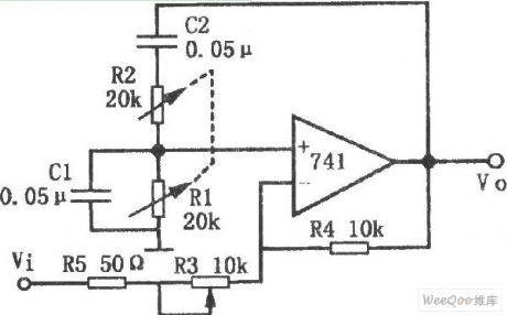
As shown in the figure is the value of Q and frequency adjustable narrowband filter circuit. This circuit shows an active narrowband filter whose value of Q and frequency are adjustable. Its positive feedback takes the form of Wien-bridge, while its loop gain is less than one. The characteristic of this circuit is that the center frequency will not be influenced by the regulation of the value of Q, because it is only relevant with the loop gain. When the gain is 600,the value of Q is 2000; when the gain is 140, the value of Q is 30. In general, in Wien-bridge oscillators, the amplifier's gain must be greater than 3 to produce oscillation for non-inverting input ends, but the gain of the amplifier in this circuit is less than 3. The resonance frequency of the circuit is:
(View)
View full Circuit Diagram | Comments | Reading(529)
Multifunctional Active Filter Circuit
Published:2011/7/14 20:21:00 Author:Joyce | Keyword: Multifunctional , Active , Filter

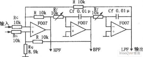
This circuit is composed of three operational amplifiers and resistance components, and its main characteristic is that it can get filtering properties of high-pass, low-pass and band-pass. In addition, once the values of Rf、Cf are changed, the bandpass characteristics can be ensured in a wide range without any interference between the circuit gain and the value of Q . This circuit is simple and easy to adjust . Also it is stable.
(View)
View full Circuit Diagram | Comments | Reading(443)
The power supply and starting circuit of Nanjing-Iveco light car
Published:2011/7/15 20:21:00 Author:Borg | Keyword: power supply, light car, Nanjing-Iveco

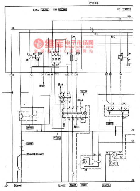
(4) power supply, starting and pre-heatingThe negative pole of the battery 20000 is bonded by the manual switch 52600, the mode of the battery is 12V88Ah (or 12V110Ah), its positive pole is connected with the central connection box 75000 by the electromagnet power supply general switch 25900, and another main stream is connected with the starter 08000, the fire wire of the AC motor 03000 is linked to the positive pole of the battery from the motor B+ cylinder. Therefore, as long as the manual switch 52600 is connected, the generator can charge the battery directly when it is running, whether the charge is normal can be indicated by the charge indicator 58100 on the dashboard.
(View)
View full Circuit Diagram | Comments | Reading(376)
CAT24C16—the E(2)PROM storage integrated circuit
Published:2011/7/15 20:31:00 Author:Borg | Keyword: storage, integrated circuit

CAT24C16 is an E(2)PROM programmable storage, which is used in the assembling circuit of Changhong 5lPT28T rear projector color TV sets to store the standard data of concentrating regulation.1.function featuresCAT24C16 contains the erasable and programmable read-only storage of 1024X16bit, IC general circuit, address signal process circuit, writing protection circuit and other additional function circuits.2.pin functions and dataCAT24C16 is in 8-pin dual in-line package, whose pin functions and data are listed in table 1.
(View)
View full Circuit Diagram | Comments | Reading(308)
The engine CMP, OKP and IOM circuit of Shanghai GM Buick-Century (2)
Published:2011/7/18 19:35:00 Author:Borg | Keyword: CMP, OKP, IOM, Buick-Century

Figure:The engine CMP, OKP and IOM circuit of Shanghai GM Buick-Century (2) (View)
View full Circuit Diagram | Comments | Reading(457)
The fuel volume sensor and oil pump circuit of Buick-Century (3)
Published:2011/7/18 19:07:00 Author:Borg | Keyword: fuel volume sensor, oil pump

figure: The fuel volume sensor and oil pump circuit of Shanghai GM Buick-Century (3) (View)
View full Circuit Diagram | Comments | Reading(418)
The air-bag (SIR) system circuit of Buick-Century (1)
Published:2011/7/18 19:12:00 Author:Borg | Keyword: air-bag, Buick-Century

figure: The air-bag(SIR) of Shanghai GM Buick-Century (1)
fuse box, SIR system, steering part and IP part, G200 (View)
View full Circuit Diagram | Comments | Reading(395)
The car body control system circuit of Buick-Regal (6)
Published:2011/7/17 22:51:00 Author:Borg | Keyword: car body, control system

Figure: The car body control system circuit of Buick-Regal (6) (View)
View full Circuit Diagram | Comments | Reading(443)
The engine power supply, ground, MIL, POM and DLC circuit of Shanghai GM Buick-Century (1)
Published:2011/7/18 19:38:00 Author:Borg | Keyword: power supply, DLC circuit, Buick-Century

Figure: The engine power supply, ground, MIL, POM and DLC circuit of Shanghai GM Buick-Century (1) (View)
View full Circuit Diagram | Comments | Reading(427)
The dashboard circuit of Buick-Regal (1)
Published:2011/7/17 23:09:00 Author:Borg | Keyword: dashboard, Buick-Regal

figure1:The dashboard circuit of Shanghai GM Buick-Regal (1) (View)
View full Circuit Diagram | Comments | Reading(389)
| Pages:46/164 At 204142434445464748495051525354555657585960Under 20 |
Circuit Categories
power supply circuit
Amplifier Circuit
Basic Circuit
LED and Light Circuit
Sensor Circuit
Signal Processing
Electrical Equipment Circuit
Control Circuit
Remote Control Circuit
A/D-D/A Converter Circuit
Audio Circuit
Measuring and Test Circuit
Communication Circuit
Computer-Related Circuit
555 Circuit
Automotive Circuit
Repairing Circuit